You can buy a balance charger, but they can be costly. A decent one costs around $150 and up plus they typically require a 12v power supply capable of a decent number of amps. So figure around $200+ for a decent setup. Of course, I never take the easy way, so I thought I'd see if I could build one of my own. I also thought it would be nice to have an adjustable charge voltage, which the off the shelf ones likely don't have.
The reason I'd like this feature is because it typically takes a long time to balance all the cells on my car. I have 9 sets of 7 or 8 cells that are balanced at once, and each of those sets takes around 5 hours to balance. And to make things worse, you have to do the whole car at once without driving it or you get to start over. So balancing takes a long weekend to complete while keeping an eye on things. If you set it to balance the cells to the same average voltage that your main charger charges to, you can do one set at a time and drive in between if you want. And while I'm talking about how long it takes, another problem is most balance chargers only balance at a rate of about 300-400 mA. If they're 3 Ah out of balance, that would take 10 hours without any help! It'd be nice to speed that up too.
So how do you do this? I've had a couple ideas, a few of which I tried out. The first thought starts with a power supply that's adjustable to 29.2 volts (3.65v x 8). You dump that into the + and - end of the 8 cell pack and monitor the cells. When one reaches 3.65 volts, a transistor turns on and off, putting a resistor in series with the battery to bypass the battery. With a 1.8 ohm power resistor, you could bypass up to 2 amps. You'd have to add some hysteresis to the circuit so it turns on at 3.65v and off at something lower like 3.5v. Here's the circuit I came up with that uses a standard op amp.
I prototyped this circuit, but had a lot of problems. Since the battery voltage drops when it turns on, the set points change and I had a very difficult time getting it to do what I wanted. After getting frustrated and doing a little research, it turns out there's a circuit there's a chip made to do exactly this! The make em for charging batteries in cell phones and other devices (go figure), so I bought one to try and prototype it. This is the picture Mouser has on their website for the part:

And when I open the package, this is what I get. Note that the space between holes on that proto board are 0.1 inches.
As you can see I tried soldering directly to the part, but that didn't work. I figure I burned it up since it's so tiny. So next I tried making a little circuit board to test it out. This process is pretty neat, you make a printout of your circuit on clear projector sheets, tape it onto a blank copper clad board that's photo sensitive, then chemically etch away the unmasked copper. Here's the circuit:
And here's the board all made up with the IC soldered in place.
And I still couldn't get it to work. I'm not sure what the deal was. The output would cycle high and low no problem, but it didn't seem to be able to drive even the tiniest of loads, so once you hooked up to anything it would stop cycling. Oh well, back to the drawing board.
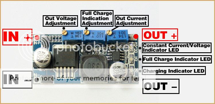
Finally, I came across this...

It's accepts a range of input voltages and the output voltage AND current are adjustable! The best thing is these puppies can be bought off ebay for around $3.50 each from China. The transistor circuit (big square thing on the left) is rated to 3 amps max. It's got all the features needed to meet all my goals, but will it? You'll have to come back later to find out!


