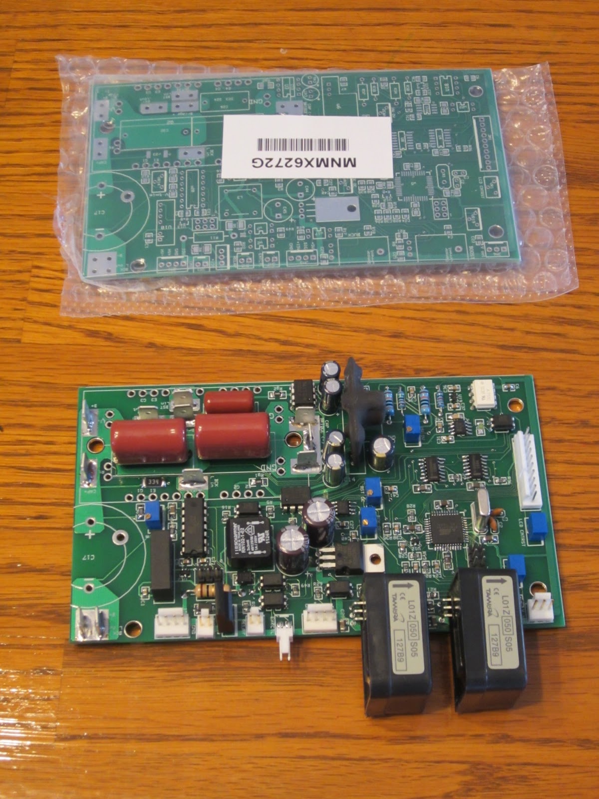
Back to the topic of the day; the charger. Part of the reason I don't have all my batteries installed in the car yet is that I have no way of charging them. In order to save money (and have more fun!) I'm building my own! Luckily I have a good friend who's blazed the trail on this one and already has a circuit designed for me. He ordered some printed circuit boards (PCBs) that he designed and now it's time to put everything on them. The boards cost more the bigger they are, but you get a real break in the price if you stick to a certain size, so Joe used a few surface mount parts to keep it within the size limit. If you don't know what those are, it's the tiny little pieces that you might see on a computer mother board that's typically placed and soldered on with a machine. Luckily we had pretty good success putting these on and here you can see the nearly finished board next to a bare PCB. You might ask why I've got two of these and that's because Joe wanted one and the minimum order is 4 boards.
The controller works like this. You plug either 115 vac or 230 vac into the controller. It rectifies the signal coming in, then boosts the voltage up to about 350 volts with a boost converter. After that is a buck converter stage that reduces the voltage to whatever is required to drive a certain amount of current into the batteries. The charger continues to do this until a peak voltage is reached. In my case it will be about 250 volts. Then the charger will vary the current going into the batteries to maintain that voltage. The current will slowly drop off, and when it goes below a certain threshold the charger will shut off.
What's a boost and buck converter? Look it up on Wikipedia. Both require a large inductor. In fact, the inductors are big enough, it would be difficult to find one that you could purchase directly. So what to do? Make your own of course! Here are the supplies: 14 gauge magnet wire and a magnetic core. I'm using 14 gauge wire because I'd like to charge the batteries fast, and that requires a lot of current. 14 gauge wire with 90 °C rated insulation is good up to 25 amps and this has 150 °C insulation so I'm guessing I should be good to over 30 amps. With a 230 volt 30 amp circuit I can get into the low 20's of amps, but I need to wire up that outlet before I can do that. At 20 amps, I could complete most of the charge for fully discharged batteries in 3 hours. After a round trip to work it would be less than half that.

Here's my 4 year old daughter helping me wind out the wires. 26 feet of wire is a lot to handle on your own!

And about an hour later, here they are! 30 amp rated 900 milli-Henry inductors! Man, my fingers hurt. And even though I'm writing this a day later...they still hurt.

Next up, finishing and testing the charger, and designing the battery monitoring system (BMS). I've also got to finish those dang battery boxes! So many details...
No comments:
Post a Comment