Saturday, November 9, 2013

Let me spin you a story about Headlight Repair

Last week I got off work a bit after 5 o'clock and it was getting a little dark out.  Suddenly I'm reminded of something I've been ignoring for months, that my headlights don't work all the time.  The problem isn't that the lights don't go on, it's that the motor doesn't always want to lift the lights up.  No big deal, the sun has just set and there should be plenty of light to make it home.

About halfway home I get a call from my wife.  She say we're going to have quesadillas for dinner tonight, and you know what make a good quesadilla right?  Tortillas.  So now I've got to stop at the grocery store and now I'm not sure I have enough time to make it home before it's too dark.  Well, the motor doesn't work immediately, but sometimes if I leave them on long enough they'll suddenly pop up a few minutes later.  Maybe that'll work for me.  I rock the switch into the first position, the parking lights go on, and two miles later the headlights decide to go up.  Perfect!  Now I can just leave them up when I go into the store.

I get to the store and realize I've never really used the headlights, so I'm not sure if they'll want to stay up when I turn off the car.  I park, turn off the ignition, and toggle the switch back to off and the headlights stay up, but the parking lights stay on.  Funny, but I can probably get in and out of the store before my battery runs dry.  I run in, grab the tortillas, and I'm back to the car in 10 minutes.  I hop in the car, toggle the switch back to parking lights only, turn on the car, then flip on the headlights...and the headlights flip back down.  Dang it!  First of all I'd apparently flipped the headlights ON before I went into the store and the lights apparently don't work anymore either, then when I thought I was turning them back on I actually turned them off and now they're stuck down.  But I hadn't quite put this together yet.

Well, I've got a ways to go through the parking lot before I actually get on the street, so maybe they'll pop up before I get there.  They don't.  But there's no traffic, it's not terribly dark, and I'm only two miles from home, so what the heck.  I pull out on the street and finally get a stroke of luck.  The lights pop up in a quarter mile and the headlights actually turn on this time!  I make it to within 100 feet of the house and the lights suddenly flick off again.  Sheesh, time to fix the headlights!

Amazingly, I find a website where a guy goes into tons of detail on how to rebuild the motor on a 944 and it looks identical to mine.  Here's the motor with the first dust cover removed and manual knob pulled off.

The whole thing is covered in this rubber dust boot, and amazingly it's totally soft still.  I figured it would want to just crack and fall apart.

Two screws removed and the case comes off.  You can see the commutator (the copper colored thing) is pretty grooved and not very smooth.

The whole rotor assembly comes out if you remove one screw with green goop on it.  I chuck it up in my drill press and sand it down with some fine grit paper.

There, nice and shiny!

Next step is the switches (which is actually the real problem.  How do I know it's the real problem you say?  Well, I actually put the motor back together and reinstalled it in the car only to find that it worked exactly as it had before.  That's why!).  You can see the switch contacts on the right that ride against this plate on the left.  There are plastic "interrupters" at the end points of travel that turn them off and on.  There was a little bit of tarnish and a few rough spots on the plate, but not much.  I sanded it down really nice and applied a really light film of dielectric grease to the surface.  The switch contacts had a small amount of stuff built up on them, so I cleaned those too.  I honestly didn't think this would make things any better, but it worked perfect after cleaning this stuff up!  By the way, don't lose the tiny ball bearing that's in the center of the plate on the right.

Apparently the required number of screwdrivers to complete this job was 5.  As time goes by, more and more tools make their way onto the workbench and don't get put away and I eventually clean the whole thing up.  There was one time when I counted how many screwdrivers I picked up and it was 18!  Apparently that's my favorite tool.

Woo hoo, the lights flip up!  Crap, the lights didn't switch on!  Well, at least I'll have something to do over the weekend right?

Monday, November 4, 2013

BMS Testing and Troubleshooting

Wow, it's been a long time since the last post, though there isn't that much I've been doing other than driving the car and enjoying the nice weather.  I've racked up 870 miles so far and still going well!

A while back my 12v battery started to show signs of age.  Before I hooked up the DC-DC converter, I had to charge it up with a regular automotive charger every night.  I noticed the voltage was getting low even after just one day of driving, then when I hooked up the converter, I realized it was causing a much higher load on the main battery pack than I was expecting.  Just to refresh you, the DC-DC converter takes power from my big 230 volt pack and turns it into 13.9 volts to run all the original electronics on the car.  Power in equals power out, so when my gauges told me that 5.2 amps at 230 volts was going in, that seemed really high.  In fact, that equates to 77 amps, so something's definitely not right (230 x 5.2 / 13.9 x 90% efficiency = 77).  I checked the actual current coming out with a clamp meter and saw 45 amps going into the battery and only 16.5 amps coming out.  After the battery charges up a bit, that drops off, but it seems to always want to take at least 10 amps to float at 13.9 volts.  The biggest problem with this is it seriously eats into my efficiency.  4 amps or so turns into 4 Ah at the end of the day, which is about 20% more than I was using before I hooked up the DC-DC converter.  Time for a new battery.

The battery in all gas powered cars needs to be big enough to pump out 600 amps or so to get the engine started.  I don't need that, so I saved some weight with a little 18 Ah AGM deep cycle battery.  That should be enough to drive for 45 minutes normally on just the battery, and around half that with the headlights on in case of some sort of problem.  And here it is!  Isn't it cute?


Here's the original for comparison.

After hooking it up, the current draw is down to 18.5 amps in, 16.2 amps out, which seems about right.  From the HV pack it's around 2.1 amps, and today on my first drive with the new battery I saw a 3 Ah improvement in my power consumption.  My next efficiency improvement will be a vacuum switch that will shut off the pump 95% of the time.  That should cut the current draw to about 0.7 amps and I should be pretty close to the original efficiency I was enjoying this summer.

So the whole purpose of this post was to talk about my BMS and I haven't even got there yet.  Sheesh, I can't believe you're still reading.  Another quick refresher on the BMS is that it keeps track of the voltage of all the batteries and makes sure they stay between about 2.60 to 3.65 volts.  I started designing the system about 8 months ago, got the wires in place about 5 months ago, finished the circuit boards 4 months ago, and finally got it all hooked up about 2 weeks ago.  I came across a post from back in June where I was optimistic it'd be working within a few weeks, ha!

Apparently I'm way behind on showing you this stuff, so here's a quick summary of where I've come.  Here's the master and 3 slave boards all hooked up to the LCD.  I'm testing a 3 cell battery on it.


Here I've got the master and one slave hooked up to the all the cells under the hood.  They're all out of calibration right now.

Here's what I spent a few nights working on, it's the code for the system.  The master has it's own code, then the 9 microprocessors on the slaves (3 each) have their own.  Unfortunately, due to a number of reasons, the #6 and #9 micros have a slightly modified code from the others.

Like I said, I got it all hooked up a couple weeks back and started to test it out.  Initially I couldn't get it to work at all, but I soon realized that in the process of modifying and cleaning up Joe's code (his isn't quite the same hardware as mine), I made it a little "too clean" and it didn't work.  I almost forgot, that since I don't have a laptop I had to drag a spare desktop computer out and set it up on a table next to the car in order to program everything!  And pretty soon it got really annoying after doing it for the 5th evening in a row, but now it's all working and calibrated...well, sort of.

I works great when the car isn't on, but when you start up the motor there's so much electronic noise being emitted that the signal is totally messed up.  I've got shielded wire, but that doesn't seem to be helping enough.  Joe lent me his oscilloscope and I tried to find the problem.

Here's what the signal looks like when everything is working fine.  Not super clean, but clean enough.

Here's what it looks like when the motor is running.  You can't even tell it's a square wave.

And here it is with the charger running.  Definitely a square wave, but kind of dirty looking, which must be confusing the master board.  A simple filter should fix this.

I hooked up a 4.7 uF capacitor to the master bus line and it didn't seem to do anything, so I bumped it up to 47 uF and then 100 uF.  Then I took another look at the schematic and realized I hooked them up in the wrong spot...doh!  I fixed the connections on the cap and got a flat line...too much capacitance.  I backed off to 4.7 uF and this is what I get.  You can see the wave never actually gets up to 5 volts even with a long space in between the pulses.  Still too much capacitance.

Here I've backed off to 0.1 uF and I still have the shark fins running across the screen.

Unfortunately, the next size smaller capacitor I have is 20 pF, which is 4 orders of magnitude smaller than the last one.  Here you can see it's not enough capacitance because it doesn't look much different than before.

Tomorrow I'll have to stop in to radio shack to find a few caps to fill the gap in my hoard.  I'm doubtful my $1.30 purchase will be very exciting for them, and they probably won't know what a capacitor is even though they'll insist on helping me, but somehow they'll still stay in business.  Well, that's enough rambling for one evening.  I'll try not to go 6 weeks before the next one!


Monday, September 16, 2013

The Need for Speed

The other day I enjoyed my first trip in the HOV lane!  Here in AZ if you have a 100% alternative fuel vehicle you get access to the carpool lane even if it's just you in the car.  To make it better, it was a Friday afternoon during rush hour, so I got to zip past all the suckers in the regular lanes while they were all going 25.  Oh yeah and I've achieved a new max speed of 72 mph.

There's a guy at work who converted a Ford Fiesta to be electric about 20 years ago.  But due to his max speed and acceleration limitations, it was nicknamed the "Siesta."  Over the time it's taken to build my car, I've been teased with the need for a similar nickname for my car, but I've been able to show that's unnecessary.  And speaking of acceleration, I've been getting the itch for a little more recently.

WARNING: The rest of this post is getting a little nerdy (okay, a lot nerdy).  If you don't like math, this might be your cue to punch out early!  I've had a few new inquiries about how this works, so it seems worthwhile to go over all this.  I hope it helps some of you out there!

During the initial testing phase I settled on a few current settings that I've yet to change.  The controller has 3 parallel IGBTs rated for 400 amps each.  Without having to reprogram the controller, I can change the max current up to 833 amps in 8 increments.  I limited the controller to output a max of about 417 amps to all but eliminate the possibility that an imbalance in the load sharing could blow one up.  I also limited the battery current to 166 amps for no real reason.  Since the car works just fine like this, I didn't want to mess with things until I got the car registered to avoid a situation where I'd have to make that 48 mile trip to downtown Phoenix on a minimum amount of testing since if something broke, I probably wouldn't have it fixed until after the 30 temporary plate had expired.  Now I've got no more excuses.

According to the specs, going from 400 to 500 amps at the motor will increase the motor torque from 67 to 100 ft-lb.  That's a 50% increase in acceleration!


Now, the way it works, just increasing the motor current will improve torque at low rpm, but once you reach a certain motor speed.  The controller adjusts the % of time the switches are turned on (duty cycle) to control the amount of current going to the motor.  But the motor requires a certain amount of voltage to go a specific speed.  According to the chart, at 72v and 400 amps the motor will spin at 2400 rpm, whereas at 500 amps it will only spin 2150 rpm.  Furthermore, at 72 volts and 400 amps to the motor, my 230 volt pack will be supplying approximately 125 amps.  At 500 amps to the motor, the batteries are supplying 155 amps.  The controller allows the motor to produce a constant torque (corresponding with the motor current) until the duty cycle is 100% or the max battery amps have been reached.  Since I've set the controller to limit battery current to 166 amps, the rpm at which the motor torque will drop off will be quite a bit lower when the motor current is bumped up.  To compensate, I'll probably need to increase the allowable battery current.

At 166 amps, the battery pack voltage sags to 215v and provides 35690 Watts.  At 400 motor amps, this is 90 volts.  To figure out the associated motor speed, you look at the chart and see 400 amps lines up with 2400 rpm at 72 volts.  The speed constant is supposed to be linear with voltage, so the max rpm I should currently get at 67 ft-lb torque is 90 / 72 x 2400 = 3000 rpm.  So this means that the motor torque will be constant up to 3000 rpm, and above that the torque will start to drop off.  In vehicle speed, that's 16 mph in 1st gear.  Do the same thing at 500 amps and you'll see the torque starts dropping off at about 2100 rpm or 11 mph.

In order to get the torque to be constant (flat) up to 3000 rpm again, I need to increase the max battery current.  Here's how I figure how much.  According to the chart, at 500 amps and 72 volts, the speed is about 2100 rpm.  3000 / 2100 x 72 = 103 volts.  103 volts x 500 amps = 51429 Watts.  51429 W / 207 volts = 248 amps (I had to do a little iteration to figure out 248 amps causes the pack voltage to drop to about 207 volts).  This is about a 4C peak discharge rate (248 amps / 60 Ah = 4.1C), which should be a piece of cake for these batteries since the datasheets have charts going up to 5C continuously.  But before I do that I'm going to check the torque on all the battery connections.  A loose connection turns into resistance, heat buildup, and a molten battery terminal that's more probably the higher your discharge current goes up.

I've harped on this before, but I love stringed instruments so much I'll do it again!  A lot of people out there want a car with huge acceleration, so they get an 11 inch motor (more torque per amp than my 9 inch motor), a 1000 amp controller, and 100 volts worth of 180 Ah batteries.  You will get lots of torque this way, but not for very long, resulting in a disappointed EV owner who's scratching their head.  The same math I showed above applies here, except it gets worse with a bigger motor because the motor.

If you look at the datasheet for the Warp 11 motor, at 500 amps and 72 volts the motor is turning about 1300 rpm.  If the controller is at 100% duty cycle (100 volts at the motor and batteries), the motor will spin 100 / 72 x 1300 = 1800 rpm at 500 amps.  In my car, that's only 9 mph.  Making some assumptions your torque vs. speed will look something like this:
0~5 mph - max torque (0~1000 rpm)  actual torque at 1000 amps ???
9 mph - 165 ft-lb (1800 rpm)
12 mph - 75 ft-lb (2300 rpm)
15 mph - 50 ft-lb (2850 rpm)
20 mph - 24 ft-lb (3800 rpm)

I don't know what the torque of a Warp 11 is at 1000 amps, but you can see how quickly the torque drops off with this type of setup, requiring you to UP shift gears to increase your torque.  Even though the gear ratio is working against you, you need the lower RPM to increase the motor current (which is what gets you the torque).  The only way to beat this is to have a high battery pack voltage to keep your duty cycle from maxing out.  If you have this controller and battery option, you may be better off with a 9 inch motor (or smaller).
Warp 9 with 100v battery pack supply and 1000 amp controller:
0~13 mph - 200 ft-lb (0~2500 rpm) this torque is an estimate
16 mph - 175 ft-lb (3050 rpm)
20 mph - 47 ft-lb (3800 rpm)
31 mph - 17 ft-lb (6000 rpm)

Alright, ENOUGH boring stuff and back to the testing!  I hooked up the laptop and punched in "t-pos-gain 5" and my controller now maxes out to 521 amps to the motor (I'm sure you already knew that because t-pos-gain / 8 x 500^2 / 300 = max current).  Like I mentioned before, that roughly correlates with 100 ft-lb of torque out of the motor, where before I was getting about 67.  Man, does it make a difference!  I can also see how I need to boost the battery current limit.  In about 1 second you can feel the jerk, and for those of you who forgot your days back in Physics 1, the term "jerk" refers to a change in acceleration (wow, I'm feeling nerdier every second here).  So in about a second, my battery current limit is pegged at 166 amps and the acceleration quickly drops off, just as I'd predicted.

I've driven the car around like this for about 25 miles now and so far the controller hasn't blown up.  It's really easy to hit the battery current limit now, so I'm not getting full use out of the 521 amps to the motor.  Since this post is already way too long (man I love talking about math) I'll end this here.  And if you have any questions, please ask!

Sunday, September 8, 2013

Burning Rubber

The other day I proved that my electric car has enough power stored up to spin the tires.  Unfortunately for me, it was a total surprise!  We'll start with a little back story.  Whenever I start moving the car, it tends to bounce forward and backward slightly.  In most geartrains, there is a certain amount of backlash and wind-up that is the cause of this.  At first it seemed a little odd to me, but I've convinced myself it's not because of the controller.  I'm fairly sure the reason a regular car doesn't do this is that the engine is always spinning, and small amounts of friction keep the whole geartrain loaded up.  In the electric car this isn't the case, so when the motor starts moving, it kind of bounces against the load of the vehicle since it momentarily spins up without any load and runs into a brick wall when all the "slack" is taken up.

Okay so enough back story.  The other day I put the car in reverse and am convinced I can keep this bouncing from happening if I ease onto the throttle slow enough.  I'm pushing on the pedal, a little further...a little further...then all of a sudden SKREECH as the tires tear loose! I quickly pull my foot off the pedal and the car stops a split second after it started.

Now at this point I'm worried that I already blew up the controller that took me 3 months to build a short 9 months ago.  The way these controllers work, the unfortunately most common failure mode of the switches is shorted, or full on.  If that happens, that means you get 100% battery power to the motor, which in my case would be 230 volts and likely over 1000 amps.  The switches are likely not rated for this kind of power and they blow up a few seconds after your car tears off into another car in the parking lot.  In my case, either the controller hardware protection, the feedback control system, or my cat-like reflexes limited it to a foot long stripe of rubber in my driveway.


After a little while I determined everything was okay and I drove to work without another hiccup.  Now I'm asking myself why this happened and how do I avoid it in the future.  I actually had this happen one time before a month or so back, but I thought maybe it had to do with the bouncing.  I came up with another idea which turned out to be true, and here it is.

The controller gets a signal from a potentiometer that changes resistance as you push the pedal down.  The controller reads the resistance and equates that to a % throttle input.  There's a dead band at both ends of stroke to account for adjustments in the linkage and a few other things.  At the zero throttle position there is a limit switch.  I use that switch to turn a contactor (big switch) that feeds battery power to the controller on and off.  The purpose of doing this is that if something goes wrong, I can take my foot off the pedal and it will immediately cut off all power to the controller - exactly the scenario I just came across.  Many people eliminate this and would have to fumble around for a manual disconnect to stop the wheels from screeching, but my method is second nature to most drivers.

Now the controller takes that throttle position and uses it to command a certain amount of current to the motor.  If you set it up to control a max of 100 amps, then at 10% throttle position it will adjust the PWM duty cycle to get 10 amps.  The switches turn on and off 16000 times a second and PWM duty cycle is the percentage of time that the switches are turned on.  More crude controllers would make 10% throttle position drive 10% duty cycle, but that causes the car to drive very abnormal compared to a regular car.

So here's the problem.  Remember that limit switch?  Well, I have to push the pedal down a short ways before that switch clicks and completes the high voltage circuit to the controller.  Well, on these two occasions I had eased into the throttle so slowly that I uncovered a problem with how I'd set things up.  The deadband before the current starts to ramp up is not quite big enough, so if done just right, the controller starts trying to drive a certain current before the contactor closes.  My attempt to ease into the throttle really slowly allowed this to happen, and I took so long the duty cycle must have risen higher than it's ever gone.  When the contactor finally clicks, that duty cycle is set until the controller senses the current has gone too high and rolls it back.  Of course, by then the wheels are already in motion.  (ha ha ha...)  Like I said before, luckily there are enough safeties in my system that the burnout only lasted a split second instead of tearing me out into the cul de sac and possibly wrecking the motor or car.  Even more lucky, the IGBTs were tough enough to endure this event unscathed.  And thanks to the design of the controller, after a couple minutes of snooping around I was able to reprogram the end points so the dead band is now big enough to work the way it's supposed to.  Something I should have done when I first set it up!

In other news, I got my cycle analyst back from Canada and am working on putting it back in the car.  While I'm at it I decided to fill in a gaping hole in the dash where there used to be a speaker grill.  Here's the hole in the dash.


And here's the old grill and new cover that'll house some LCD screens and buttons.  Now I just need some flat black paint.


Tuesday, August 13, 2013

My Audience

Last week was a bit of a cliffhanger, so I think I need to finish (or at least update) that story.  You may remember I had a nicely charred connector going into the back of my fuse/relay box.  After a staring at it for a while I finally concluded that this wire was the 12v supply for my headlights.  Makes sense since the headlights don't seem to be working.  I clipped that wire off and plugged the connector back in and everything's working identically to how it worked before.  All I need now is the right bullet connector to put that wire back in and hopefully my headlights will work again.

In other news, the blog recently passed 10,000 views!  I had no idea it would turn out to be so popular.  The pace is getting ever faster too because in the last month alone I've had nearly 1,000 views.  It's also interesting to see where people are who are checking it out.  Some of the top hitters are United States, UK, and Germany, which all make sense since I know people in all those locations.  However, there are tons of people checking in from places I don't know people from like Latvia, Russia, Sweden, Australia, Ukraine, and the list goes on.  Even more fun than that, I get occasional emails from people with questions or comments, like my new penpal from the Ukraine who is converting his own Porsche 924!  If you've ever thought about it, please feel free to send me a message.  I love talking about my project, just ask my wife!  On to the latest progress...

This is a good time to check what's left to do (not that it'll ever be 100% done).
- I still have not finished installing and programming the BMS
- I need to install the DC-DC converter
- The charger could use some more optimization to boost output and efficiency
- There are a number of cosmetic things that would be nice to fix

For some reason I've been ignoring the BMS for a while.  Probably this is because it would be nice to have a solid day or two to install, debug, and calibrate the whole thing.  Even though it really shouldn't affect things, I feel like anything hooked up to the HV system shouldn't be in a state of debugging for an extended period of time.

Not having the DC-DC converter in has been inconvenient for a few reasons.  First, that would have avoided that first breakdown, and second, it's a pain to have to charge the 12v battery every night.  I actually started installing this just the other day.  I've got all the wires attached to the converter and mounted it, I just need to make the connections to the HV and 12v batteries now.  This is a Meanwell HRP-600 12v power supply.  It can put out up to 53 amps, and costs only $130, which is a steal compared to the DC-DC converters you see on EV websites that are "designed for EVs" that cost hundreds of dollars more.  Here it is with the wires hooked up and before I put it in the car.


The two little wires go to the HV battery +/- terminals, and the 10 gauge wires go to the battery terminals and the body.

Speaking of breakdowns, I also mentioned a while back that after the 12v battery died on me I still had problems after charging that battery.  I believe if figured out that problem.  In the process of troubleshooting, I wiggled the connector that plugs into the control board in the motor controller.  I'm pretty sure that either the 12v or ground pin on there was loose.  The wires are probably a little too short and were pulling on the connector.  "Soon" I will replace those wires with longer ones and recrimp the pins.  If the problem comes back I'll just solder them directly to the board.  For now it seems to be working after going back to the old wire.  I've had no problems in the last 50 or so miles.

The charger probably will get another look when I install the BMS because I'll have to reprogram it to accept a BMS input.  Until then I'll settle for 4.3 amp charging rate out of a standard outlet that doesn't seem to trip the breaker (unless I'm also trying to use my electric lawn mower).

As far as cosmetic work on the car, I replaced all the hardware for the sunroof.  Now when I take it off, the wind dam doesn't want to dangle in my face while I drive!  The next thing to do is get a new interior light that's dangling in front of the rear view mirror from its wires.  That and the lack of a driver's side sun visor and window crank knob are really annoying!

Well, I've taken up enough of your time for one post, plus I need to put the kids to bed!  Next time I'll tell you about all the problems I'm having with my cycle analyst.

Wednesday, July 31, 2013

Good News, Bad News Part 2

Good news everybody, the Porsche is finally registered!


The other good news is I can finally charge the car without having to open the hatch and the hood.  I installed this spiffy outlet where the gas tank fill spout used to be.  I also got a nice 12 gauge cable so I don't have to worry about overheating the wires anymore.


Now for the bad.  I also had my first breakdown!  I was driving to work and I suddenly lost power.  Luckily I had enough momentum to easily coast into a parking lot.  I realized the voltage on the battery was way low and quickly remembered that I haven't charged the auxiliary battery in about 80 miles!  I conclude that the power to the controller was so low that the brownout feature on the microcontroller shut it down before it started malfunctioning.  My kind and loving wife picked me and the battery up, I hooked it up to the charger, and took the jeep into work.

After work I pick up the battery and my wife drives me back to the Porsche.  I plop the battery in and away I go.  I'm about 7 miles from home and after 5 miles, the car starts shutting down again.  Now I'm not feeling so good because the voltage still reads okay.  I figure out that if I take my foot off the pedal, the controller seems to reset and I am able to limp home.

After thinking for a while, a friend comes over and holds the laptop for me while I drive.  The same problem keeps coming up, and luckily I get a clue from the RTD program.  When I lose power that the controller sends restart info to the RTD program, so it appears that the controller is momentarily losing power.  When it regains power it goes into "high pedal lockout" mode.  The controller will sense if you have your foot on the pedal when it starts up and won't allow the PWM signal to start until you take your foot off.  That explains why I can lift my foot off the pedal and keep going.

So now, what's causing this?  I've got a few theories and I try running a dedicated wire straight from the battery to the controller.  Luckily, this seems to work!  I drive 4 miles and have no problems compared to at least a dozen restarts in the previous 4 miles.

There's a relay I put in to power all the stuff I added (controller, pumps, fans, etc.) and it turns on with the ignition.  I've had problems from the beginning that the instruments seem to have a bad ground or something.  A fresh 12.5 volt battery only reads about 11 volts.  The headlight motor doesn't work either (forums tell me that anything less than 12 volts will cause this to not work) and when the headlights go on, the voltage drops even more.  In fact, it seems like turning on the blinkers would cause the controller to cut out.  I'm thinking the voltage gets low enough that the relay loses power and flips off momentarily.

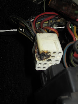
I've known I need to fix this for a while, and it seems like now is the time.  I checked all the ground connections, and those seem to be good.  I look at the fuse and relay box and find a couple of loose wires!  Unfortunately, it is not obvious at all where these go, but it doesn't appear that they have anything to do with grounding or the headlights.  I snoop around for a while, and suddenly I see this!


Gah!  I'm pretty sure this is one of the 12v power supply lines going into the fuse and relay box.  This must have been loose for a while and the poor conductance built up heat and eventually fried this connection.  I have no idea how long it's been like this, and to my knowledge I've never messed with these connections.  I'm not sure how I'm going to fix this but I'll have to reroute power to the fuse box.  Hopefully this is the problem!

Let's end on some good news.  I've racked up 235 miles so far, so I've almost saved an entire tank of gas!  I can feel the savings rolling in!

Friday, July 12, 2013

Officially Electric

I finally achieved one of the major goals today.  Here's my story!

In order to register your vehicle, you have to have your car emissions tested.  Unfortunately, not having a gas cap or any of the emissions equipment the car was originally equipped with, I can't pass this test even though I'd pass the intent of the test.  So I basically have to have the emissions test waived.  To do that, I have to get an "Alternative Fuel Certificate" issued for my car.  To get that, it must be inspected, and unfortunately, that cannot be done any any old MVD office.  In fact there are only two offices in Arizona, the closest of which is 21 miles from my house.  I guess it could be worse if I had to go to the Tucson office.  My design of the car was for a 50 mile range, so that doesn't leave a lot of room, especially when you consider you can't test much until you get the car registered!

Luckily, there is a 30 day temporary registration option that I got back in mid June.  I've racked up 137 miles of testing since then, the longest trip being about 25 miles.  One thing I learned is my range is theoretically greater than I was planning.  The car is more efficient, ranging from 200-240 Whr/mile depending on how many lights I hit, and I was designing around 275-300.  Another way to look at it is I get a little more than 1 mile per 1 Ah on the batteries, and since they're 60 Ah batteries, I should get 60+ miles.  Of course I haven't really tested this yet, but it makes me feel a little better.  Also lucky, my friend, Joe, lives about 6 miles from the inspection office and he offered to let me charge a couple hours before I made it rest of the way home.

With my 30 temp plate expiring on Sunday, I took the Porsche on the journey this morning.  The most direct way to get there is on the highway, so I decided to add that to my list of new things to do for the day.  The car had no problems speeding up and keeping up with traffic.  I even got up to 70 mph at one point!  I pulled into the inspection area after consuming 19.5 AHr.  Three guys hop out of a little hut and come check out the car.  98% of the questions they ask have nothing to do with the paperwork they needed to do, and one guy even pulled out a camera for a few pictures!  One of them said they hadn't seen an electric conversion in over a year, which surprised me.  I'm guessing the electric vehicle tax incentive that went away 18 months ago has something to do with it.  5 minutes later I'm back on the road with my embossed certificate!

6 more miles to Joe's house and I stop to add about 14 Ah back into the batteries.  Then I'm headed back home.  About 2/3 of the way home a sickening feeling enters my stomach as a terrible melted plastic scent fills the car.  I feel slightly better when I see a truck pulling onto the shoulder with his hazards on, and much better when I pass him and the smell goes away.  10 minutes later I'm safely home with 48 miles under my belt for the day.  I figure I'm about 30 Ah down, so it'll take about 6 hours to top the batteries off again.

Now I just need to make a stop at the MVD (yes another one) to get the registration taken care of.  I'm hoping to get one of those alternative fuel license plates with a custom number.  I'll let you know what I decide on.  18 months, and the car is finally legal!

Saturday, June 29, 2013

More Driving Stats

I've had the car registered for almost 2 weeks now and have racked up 90 miles of driving. I had some clients from Boeing in for a review at work this week and I got to impress them with the car.

Efficiency tends to be in the range of 210-240 Wh/mile depending on how many times I have to stop. I've got RTD explorer working and tracked the temperature of the controller. On a 103 °F day it got up to a peak of 129 °F at the end of an acceleration from 0-50 mph and quickly drops down to 124 °F. If I coast to a stop at a light, it's down to 117-120 °F within a few seconds and seems to stabilize there. So I'm guessing the temperature of the coolant in the system stabilizes to around 117 °F or less (<15 above ambient?) since it's no different after 11 miles of driving.

I've been experimenting with charging. I don't have a heavy duty extension cord yet, so I have to string two regular (probably 16 awg) extension cords together. Originally I had an old computer cable pigtailed to the inlet wires in the loop too. That was bad because that wire was 18 awg and it got hot! All the internal wiring is 10 AWG in anticipation of wanting to charge at 20 amps or higher. If I charge the car at 5.0 amps, the clamp meter reads 14.5 or so Amps rms in from the house 120v line, and a 15 amp circuit breaker would eventually trip. So I've either had to drop down to 4.0 amps or run a third extension cord through my garage door and plug into the 20 amp outlet in the laundry room. Not great for charging when it's 118 °F outside. At 4 amps it takes about 5.5 hours to charge 22 miles (around 21 Ah). At 5.3 amps it's down to around 3 hrs 50 min. When I get a 240v 30 amp outlet installed and am brave enough to try it, I should be able to charge it in about an hour if the charger doesn't get too hot.

In the meantime I've been working on the BMS. The head board is complete and one of the slaves is complete. I've been modifying the code Joe sent me and think it's about ready to test. Unfortunately I completely missed a bunch of connectors in my order and have to wait until July 2nd for Mouser to get them here, so I can't do any testing until then.

So with no car work that needs to be done, I'm focusing on a few things I've been neglecting around the house. My wife is really happy that I cleaned out the garage and she can park in there again! I also tried my hand at cleaning the air conditioner to try and make it more efficient. The bozos who installed the unit in my attic put it in backwards so the access panel faces into a wall! I've had problems with it not draining properly because there's a bunch of sludge built up in the drain pan that I've never been able to clean out. Well, we've got a ton of family coming over on Sunday and it's supposed to be around 118 °F out so it needs all the help it can get so I bite the bullet, got up at 5:30 this morning and head up in the attic. After nailing down some boards I can lay down on and an hour and a half of cursing I managed to get the access panel off. Another hour and I've vacuumed all the sludge out and sprayed down the evaporator coils with some cleaner. Hopefully it was worth the effort. It's currently 115 °F outside and 76 °F inside. So far so good but the forecast is for 122 today.

I've only got two more weeks on my temporary permit to test out the car. I'd love to have the BMS functioning by the end of that before I take the 40 mile trip to the MVD, so hopefully I'll have enough time over the 4th of July weekend to make that happen.

Stay cool!

Monday, June 17, 2013

Free Parking

Today was a momentous occasion for me, I finally drove all the way in to work and back!  My employer has  a solar array in the parking lot and they lease shaded parking spaces under there.  But there are a few fortunate people who get free spots for 100% alternative fuel vehicles, carpooling, and hybrid vehicles (in that priority).  I pulled into my spot this morning even though I didn't have a permit yet (they've had one set aside for me for about two months now, but wouldn't give me the permit until I started driving the car) and within 3 hours I already had my first parking ticket!  Luckily there's no substance to the ticket, and I now have my permit so I can park legally from now on.

Here are the stats from today's drive.
According to Google it's 11.2 miles each way, so 22.4 miles total.
Total energy consumed: 4792 Wh
Energy per mile: 214 Wh/mile
Theoretical max capacity of the battery pack = 3.3x70x60 = 13.68 kW-hr
% Battery consumed: 35%
Max battery amps: 162 A
Minimum battery voltage: 216 V

Unfortunately, RTD explorer apparently experienced a user error and I didn't get any data from the trip other than when it first started up.  Mostly I was wondering how hot the controller would get.  It started out at 104 °F and finished hot to the touch, but not so hot you couldn't keep your hand on it.  So maybe 120 °F at least on the outside?  Not too bad.  Now I get to sweat through 4 hours of charging.  Speaking of sweating, pretty soon I'm gonna need to get the AC working!

Sunday, June 16, 2013

On the road

Happy Father's Day to all you fathers out there.  Today I celebrated by driving the car to church!  At 5 miles each way, this is my longest drive to date.  I got a  30 day temporary registration on Friday, so I've got a nice amount of time to test things out before taking the 20 mile (each way) drive into Phoenix to get all the registration stuff sorted out.

I didn't want to get the 30 day tag until I knew I could recharge the batteries, which means I can recharge the batteries now!  Last Wednesday was the first test.  Here you can see the mounting location for the charger.


Of course, mounting the charger means making another bracket.  Man, I've made so many darn brackets.  They look so simple, but to get this charger in took two full evenings of measuring, cutting, and welding.  Thankfully this is the last major fabrication I have to do at least in the foreseeable future.  As you could see in the picture above, I still don't have the charger permanently wired in yet, which is good.  I've had a few minor issues to deal with and reprogrammed it a couple times.  The voltage sensing circuit had to be calibrated, and I keep getting an occasional safety fault that trips and shuts things down.  Here's what it looks like when it's charging.


Set is the current setting.  Out is the actual current going into the battery.  IrmsIN is the RMS current coming in from the wall (not right at the moment). BMS is a signal from the BMS that tells the charger the max current it will let it charge at (currently hard fixed since the BMS isn't finished yet).  Then on the right, the top number is the voltage it will charge to and the one below is the current voltage.  The fourth like is the IGBT temperature, and finally the time it has been charging.

On Thursday night I'd worked out a few bugs and charged all the cells up.  I think 51 °C was the max temp I saw.  Considering it's about 100 degrees F out, that's only a 23 °F rise in temp, which is good.  On Friday, after getting my temp tag I took the Porsche on its first real trip - 1 mile each way to the grocery store.  Then today I put in another 10 miles.

I hooked up some instrumentation that keeps track of the voltage, current, and total energy consumed (among other things), so now it's time for a little post-trip analysis.  For some reason it didn't turn on for the first mile, so I only have data for the proceeding 11 miles or so.  I maxed out at 163 Amps to the batteries.  I have the controller set at 166 Amps max, so that checks out.  The min voltage was 203 volts, so if the nominal voltage was 235 (resting voltage), that's about a 14% sag at 2.7C discharge.  I'm guessing that most of that isn't due to the batteries, and mostly attributed to the 90 or so connections in the string.  If none of the sag were due to the batteries, that's about 2 milliohms per connection.  That's good enough for the aircraft industry, so it's good enough for me.  I consumed 2,345 Watts, so that's 213 W/mile.  Granted 11 miles is only an estimate, but that's really good for an electric car.  Also, I was consuming slightly less than 1 Ah per mile.  The cells are supposed to be 60 Ah, which implies a better range than I was originally expecting.

Soon I'll be hooking up the charger for good, which means I need a fancy plug in place of the gas cap.  I picked one of these up online.  It's a charging port for a boat so it should be fairly weather resistant.  I need a disc of metal to mount it to.  Unfortunately, I don't have 7/8 inch and 3.60 inch hole saws to cut it out with.  Luckily I'm still borrowing my buddy's lathe, so here goes nothing!


I'm making a lot of progress on the BMS.  Hopefully I'll have more to share on that soon...

Tuesday, June 4, 2013

The Master

I had an evening at home with the kids so I decided to watch a movie with them and put together the BMS master board.  

So, master board, what what's a typical day look like for you?  
Well, I take the battery info and give it to the charger and driver.
So you physically take the battery info and give it to the charger?
Well, no, I have cables that do that for me.
So, what is it that you actually do do?
I've got lots of IO's!  I know how to talk with an LCD!  I've got processing power, can't you understand that?  What the hell is wrong with you people?!


In other news, I finished top charging all the batteries, so now the total pack voltage is around 246 volts.  Time to take it for a spin!


There's a 35 mph zone in the neighborhood, so that's my first stop.  One mile up and back and I've got the need, the need for speed.  Out on the open road (well, Gilbert road at any rate) I do a 2.5 mile loop, max out at 50 mph and return home for a total of around 4 miles!  Now's a good chance to see if any of those connections are a little loose, which you can do by touching each one to see if it's hot (with your other hand in your pocket to avoid a deadly shock of course).  Everything seems in order.  The laptop battery wasn't cooperating, so no data from the controller.

The next day I can't help but boost the current to the motor.  Previously I'd had the motor current set to a value of 3, which corresponds to 3 / 8 x 500 x 5 / 3 = 312.5 amps of course.  This time around I toggle it up to 4, or 416.7 amps max to the motor.  The battery limit is still set to a value of 100, which anyone knows corresponds to 166.7 amps, right?  I take a spin around a 4 mile block and check the stats.  Controller temp has reached 102 °F (39 °C), both the motor and battery currents maxed out, I consumed an approximate 1 kWh, and I've got a huge grin on my face!  The battery current limit is actually limiting me to around 55 Hp, so I'll have to bump that up next time around.  Booya!

Tuesday, May 21, 2013

Motor Controller Part 5: The controller strikes back

Last time I was working on doing wiring on all the batteries.  I'd run out of time to finish it before our friends Toni and Warren visited us from Germany.  But between beers and while the girls were playing video games, Warren and I snuck out to get a little work done.  We started by finishing the routing of the 2/0 cables.  I got the cables securely tied up under the car so there's no chance of a stray stick snagging it.  Warren is sitting here with a phone in his hand.  He punched in 9-1, and if the car falls on me he'll just have to hit 1 again.


After finishing the large cables, it was time to finish the small wires.  You can see all the BMS wires are hooked up in the front and we got all the connectors pinned out.  I also wired up the the B- contactor and the vacuum pump.


Here's a close up of those connectors I keep mentioning.  There are three that plug into the BMS boards.  I'm also using them to initially top charge the batteries.


Here are the two clusters of wires coming out the back end of the car.  Finally the spaghetti of wires are neatly bundled into wire looms and all fitted into connectors.  Now I just need to drill a hole into the cargo cubby hole that's behind the wheel well  and stuff the wires in there.


Alright, what's next?  Hmm, can't think of anything else that needs to be done...I guess it's time to test out that controller again!  Just a reminder, I've driven the car about 3 miles on 1/3 of the battery pack.  That's about 80 volts.  Well, a lot of the reason for the custom controller is that I wanted to run higher voltage than 150v, so I really haven't proven anything yet.  An 80v 300 amp controller is pretty common out there, but a 230v nominal controller, that's special and seems to cost $2400-$3800.

Well, no more lollygagging, let's see what happens.  I flip the manual disconnect and that connects the positive side through the precharge resistor.  Next I flip the ignition to engage the B- contactor and that closes the loop and allows the capacitors to charge up.  If something blows, the voltage here probably will be less than the pack voltage, but since the 1k ohm precharge resistor is the only path for current to flow, the current is limited to 1/4 amp and the damage can be minimized.  Once that's bypassed by closing the contactor, the controller determines the amount of current, and if that fails closed it'll be a couple thousand amps.  Booya, 235 volts!

Okay, don't get too excited, it's possible that something still hasn't surfaced yet.  I opened up the manual disconnect and discharge the capacitors by pushing the pedal.  0 volts, so that checks out.  I decide to redo that cycle a couple times just to make sure there's no problem with the caps charging and discharging with no problems.  In the pic below I had opened the manual switch for a while and the voltage reading actually drained the charge a bit to 231 volts.  So now for the real test.  At this point I also hit the "start" button to close the B+ contactor and remove any limitations on battery pack current other than what the controller does.  I put the car in neutral to avoid a runaway and push the pedal...


Aaaahhhhhhhh!  Oh the humanity!  At least I've got insurance now.


Just kidding...the motor just spun like it's supposed to.  Though the picture above represents some of the nightmares I've been having over the last couple weeks.  Here's what the car really looks like now.  After slowly working my way up to it, I drove a whopping 0.1 miles to pick up my daughter from a friend's house and successfully made it home!  Woo hoo!


Next up, time to start installing instrumentation and get ready to take it to the DMV!

Wednesday, May 15, 2013

Wires, wires, and more wires

The batteries are all finally mounted in the car.  To get here I spent months designing, fabricating, fitting, modifying, refitting, and finally bolting in the battery racks.  It was a lot more difficult than I imagined it would be, but I guess that's par for the course for such a custom car.  Now that the batteries are strapped in place it's time to wire them all up.  Each of the rear battery clusters has 23 batteries, 46 bolts, 92 washers, 1 fuse, 2-4 copper bars, 22 bus bars, 3 twisted pair wires, and 24 BMS wires.  The next step in wiring these all up is to build the BMS wires.

The BMS wires serve two purposes.  When the BMS functions, a very small amount of current is flowing through the wires while the circuit board monitors the voltage across each cell.  The current flowing out of one cell is not exactly the same as all the other cells in the cluster, and I'm estimating after 3 months, some will be around 1.5% more discharged than others (about 1 Ah).  Eventually, this will cause the charger to stop charging prematurely and the cells will need to be re-balanced.  The BMS boards each have three balance charging ports, and a balance charger will send current through those little BMS wires to do just that.

Each wire comprises a ring terminal where it is bolted to the battery, a 4 amp fuse, and the wire.  To put these wires together I had to crimp the terminal to the fuse and solder it in place.  Without the solder joint, there's a chance that the crimp could come loose and cause some faults.  How do I know this you ask?  Well, I'll just say that Joe highly advised the solder joint.  So clip the fuse to size, crimp on the ring terminal, solder the fuse lead, solder the wire to the fuse, cut the wire to length, heat shrink over the fuse connections.  That should be too bad right?  Only a couple minutes and you're done.  If you add it all up, that took about six and a half minutes.  Multiply by 73 and that's how long it took to make all these dang wires!


Ok, the next step is to hook it all up.  One of the terminals on each battery is aluminum.  When you put aluminum and copper together you have the potential for galvanic corrosion.  To get around this, you put a little conductive anti-corrosion paste and rub it in with a wire brush.  After I got everything installed, this is what it looks like:


To keep things straight I got some sticker number flags and put one on both ends of each wire.  Amazingly some places want to charge you $20 for a sheet of these stickers, but luckily I found some on Amazon for just a couple bucks.


Yeah yeah yeah, I know I'm missing one wire and I forgot to put the fuse in (if you look two pics up).  And no, I swear I didn't do the exact same thing to the battery pack on the other side...I was up until 12:30 last night getting this done, so cut me some slack!  So far, so good.  Now I bundled all the wires together, zip tied them about 700 times, and collected all the ends.  They're not all the same length anymore, so I have to retag them and cut them all down to the right length.  I've gotta be really careful though because each of these are live wires!  If I'm unlucky enough to touch two wire tips together I'll have to spend another 13 minutes making new wires plus another 30 minutes swapping them out.  That also means don't clip more than one wire at once!  So I clip, strip, then crimp a connector pin onto the end of each and now I've got three plugs to go into the plugs of the BMS circuit boards.  I've got all the wires mounted on the batteries, but only 1/3rd of those connectors have been pinned out so far.  Oh yeah, and I'm missing one wire.

I also got all the large 2/0 cables measured, cut, and crimped with lugs, so theoretically I'm all set to test out the controller on 230v.  I just have to screw it all together.  I'm a little battery weary and we've got friends visiting this weekend, so I'm not gonna push it an do something stupid in the testing phase.  So after a weekend of R&R I'll be back next week to see if I can keep the magic smoke in the controller!

Friday, May 10, 2013

Need more volts

Previously I've been driving the car around on just 1/3 of the batteries, or about 80v, but now it's time to put the rest of the batteries in there.  In the back of the car below the floor I have two battery racks that hold 23 cells.  Actually, they're big enough for 23 each, but I only bought enough for 23.  I guess if later on I want 2/70ths more range I can buy two more cells.  At any rate, the way the batteries are tied down, I can't just leave that empty space open so I need a battery "blank" to fill it in.  My father in law has a ton of scrap wood and woodworking tools, so he helped me put a pair of these together.


As part of the battery monitoring system I added the capability to monitor the temperature of the cells, three spots in each cluster of batteries.  To do that I've got some thermistors, which are resistors that vary resistance as a function of temperature.  Here's one of them soldered onto a wire.


Apparently there's a lot of debate of how to "properly" monitor the temp of your cells.  Some people attach the thermistor to the posts on the cell since they're wetted in the electrolyte.  Other people using lead acid batteries will actually put the thermistor inside the battery so it's directly touching the electrolyte.  I'm going simple and just taping it to the side of the battery like this.


Then I loaded all the batteries in those nice racks in the back and clamped and strapped them down the same way I did with the front batteries. 


Pretty clean look from underneath.  You can see the threads on the four eyebolts that are really easy to access here.  Too bad the aluminum clamps are super difficult to get to, but oh well.


Well that's it for now.  This weekend I'll start wiring it all up!


Thursday, May 9, 2013

Charger Part 3 Plus Other Stuff

I'm moving along pretty fast now and the next thing I want to do is get the batteries charged before I mount them in the car.  Once they're in the car, it'll be a lot more difficult to do without the big charger, and most of them are not balanced.  Here are the remaining 46 batteries hooked up to the mini charger.  Just 30 hours and they should be ready to go!


The batteries already in the car have already been balanced as a set, so I can charge them all at once if I have a charger big enough to do that.  Last time I started smoking the charger due to a short circuit through the inductor's magnetic field that created an inductive heater.  In this picture you can see the metal bracket that holds the inductors in place loops right through them and the screws complete the circuit with the case.  It's gotta go!

 Here you can see my solution.  I've taken a plastic pipe and used it to hold the inductors in place.  All fixed, at least I hope so!

I realized I ever showed a full picture of the charger, so here it is.  Due to some rework, the "Batt" and "AC" labels are unfortunately backwards.

The big capacitor is one of the few remaining parts to be strapped down in the charger, and here's how I plan to do that.  You can also see the fan that'll blow directly onto the inductors to keep them cool.

Apparently after this I didn't take any pictures, so you'll have to take my word for it.  I hooked the charger back up to the car and plugged her in.  After a few minutes charging at 2 amps, still no smoke so I ramp it up a bit.  Over the course of 20 minutes I get the courage to boost it to 7.5 amps into the battery pack and so far so good!  The inductors are a little warm to the touch, but not bad.  Should be better when the fan is blowing on them.

The way these batteries work, they are close to 3.3 volts over most of their charge/discharge cycle.  During charge, the voltage will get up to 3.37 volts for ages.  As they approach a full charge, the voltage will start to rise faster and faster.  Since I have no BMS hooked up, if one of the batteries happen to be more charged than the others, the voltage on that one will start to rise while the others are still stalled out around 3.37 volts.  To avoid having some batteries start smoldering, I was checking to voltages every minute or so.  The charger is programmed to raise the entire pack voltage to 3.45 volts per cell.  Once it gets to that point, the charger will back off on the current to maintain that voltage.  The current will slowly decrease and the charger will turn itself off after it drops to 2 amps.  Amazingly, that's what happened!

So that's not even close to how far I've gotten on the car since last time, but I've been picked away at this post for 3 days so it's time to POST!  Maybe next time I'll be testing the car on 230v...