Monday, July 9, 2012

Motor Adapter is in and the motor spins!

It's been a while since the last post.  Not because I haven't been getting any work done, but I've been delinquent on updating the blog.

I finally got one of the last pieces I needed to get the motor installed in the car.  The old engine mounts to a bellhousing and I needed an adapter plate that would allow my motor to mount to it instead.  A friend of mine at work knows a guy who owed him a favor and also happens to run a machine shop with CNC mills.  I bought a huge block of aluminum (15 inch diameter by 2 inches thick) and sent that plus a CAD model of the housing I wanted away back in February and 10 weeks later it came back weighing about a two thirds less.  The only downside is it cost $300 more than the free me and my friend were expecting.  Oh well...


When designing it, there were a few real important things to consider.  The most important was getting the motor lined up as perfect as can be with the drive shaft.  There are two alignment features that were part of the engine block that I needed to recreate.  There are also about half a dozen bolt holes, but due to space it wasn't very easy to accurately measure them all.  I decided to only dimension the alignment holes to the motor pilot hole and plan to drill all the bolt holes after I got it back.

Many vehicles have alignment pins, but mine have bolts going through them, so they're actually alignment cylinders.  In order to avoid having to pay for a 2.5 inch thick block of aluminum and a lot of extra machining I decided to press in some cylinders myself.  Of course, you can't just buy something like this so I borrowed my friend, Ara's, lathe and made some myself.  The fit was super tight, but with a clamp and a big hammer they both went in!  You can see them poking out in the pictures.

The other thing you might see is a block of aluminum sticking out the side (upper picture).  Before I bought the block of aluminum I hadn't modeled up the part yet and didn't measure something right.  As it turned out I would have needed a 17 inch diameter block to get all of the holes onto the part.  After figuring this out I decided to bolt a block on to catch the last of the holes.  It'll be on the bottom, so unless you're reading my blog you'll never know!

Another thing I wasn't sure of was what orientation I would want the motor when I put it in the car.  In the end I decided to have the machinist cut 8 mounting holes for the motor instead of 4 so I have an option every 45 degrees.

The next thing I did was try putting power to the motor!  I hooked up the flywheel to my new flywheel adapter and clamped a battery to it.  I was a little disappointed to see it has some vibration.  I took the flywheel off and hooked it up again, and it had about the same amount of vibration!  Looong story short, I was able to clock the flywheel differently and everything is really well balanced now, so the adapter alignment and flywheel balance are similar to the balance that the motor manufacturer put into the motor.  When you think about that, that's probably as good as you could hope for.

Next I started working on mounting the motor in the car.  The motor will have a band that goes around the center of it.  From that band there will be arms going to the left and right that attach to motor mounts.  I got some Jeep Cherokee mounts because they're a good shape and pretty cheap.  The motor mounts will bolt onto a pad that I'll weld onto the front crossmember of the car.  I started by cutting out those pads, which quickly became more complex than I originally thought.  It turns out the crossmember is curved and not flat, so I had to get creative in getting the shape just right.  But after a little while with the grinder they fit really nicely.  Next step will be to weld those in and bolt on the mounts, but that'll be next week.

Here is the band I've bent to fit around the motor.

Here is the tool I made to bend the band.  I wanted a smooth curve and not a bunch of kinked corners, and this did the trick. 

Here is the passenger side motor mount pad.

Here is the driver side pad and motor mount.


Still not done with this update!  I have been designing the liquid cooling plate for the motor controller for quite some time.  I bought a block of aluminum with the intent of making two of these (one for Joe) and then realized I didn't have a good way to cut it in half.  Six square inches of aluminum is a lot to cut through even with a reciprocating saw.  Luckily my father in law has a vertical band saw that did the trick.  I'll follow up with a post later on that shows how it'll look when I machine the flow passages.

And finally, I got some work done on the dashboard.  I bought some vinyl fabric a while back and trimmed it out to the right shape.  There are some dash overlays you can buy that do the same thing, but cost about 5x what I'm spending, so if this goes badly I can always revert to that.  The overlays just cover the upper half of the dash so that's what I plan to do here as well.  I sprayed the dash and the back of the vinyl with 3M spray glue, let them both dry for 5-10 minutes, then stuck them together.  I still plan to epoxy the edges down, but on the most part it sticks pretty well.  There were two areas that were impossible to stretch the fabric over, so I trimmed those sections with neat, straight lines so hopefully I can patch in another piece to fill the gap without more than a hairline joint.  So far so good!

Old

New

If you've read this far, you must truly be one of my fans...thanks!  I'll try and keep up more often so they aren't so long in the future, but I'm not making any promises...

Wednesday, May 30, 2012

Dashboard Repair Part 1

It's been a while since the last post, but I've still been making some progress.  I recently started an attempt to repair my dashboard.  The Porsche dashboards didn't stand the test of time well.  In fact, a friend of mine at work said he bought one the same year and color as mine when it was 4 years old and it already had cracks in the dash.


The options here are dash mat ($40), dash overlay ($150), refurbish ($400), new replacement ($1400 if you can find one), or something altogether different.  You can guess what I'm going with...I got this idea from a guy online who fixed up his MG dash.  The idea is to fill all the cracks with silicone, then glue a new piece of vinyl fabric over the top.  First step is to clean it up and flatten it out.  The edges of all the cracks are curled up, so simply filling them in wouldn't make a flat surface.  I sliced off the curled edges and dug out all the loose foam.

Now I'm ready to fill the cracks.  I got some black silicone, worked it into the cracks, and smoothed it over with a putty knife.  So far so good!


The next step will be to trim and glue the vinyl fabric on, but I have to wait for it to dry for a while so more on that later.

On another note, my adapter plate is nearly done!  I should be ready to fill this void with the electric motor soon.


Here's the nearly finished adapter plate.


Sunday, May 6, 2012

Dashboard Removal and Odometer Repair

I plan to flush the A/C system and replace the heater core with an electric heater.  Plus, there are problems with the blower motor and who knows what else.  Basically I need to take the whole thing apart.  I finally bit the bullet and started taking the dash out.  There are only about 4 screws and one nut holding on the dashboard, but it's certainly not that simple.  I pulled out the manual and look up dashboard removal, and to my surprise, the first step is to remove the sun visors!  Wha?!  Eventually it makes sense though because you have to remove a headliner to get access to the panels on the pillars.  Then with those removed you can get to two of the dash screws.  The other two screws and the nut are easy to remove, but I'm still far from being done.

The next step is removing the steering wheel.  Quickly I find out I don't have the 24 mm socket to do the job, so I'm sunk for the night and pick one up on the way home from work the next day.  There are a surprisingly large amount of wires going into the steering column.  Luckily it's only three plugs that need to be disconnected.  After I get this out of the way I find something peculiar.  The steering wheel would make this funny squeaking noise when you turned it.  It turns out that was due to a broken off reciprocating saw blade that was jammed into a clamp that was scraping on the steering shaft.  I've got no clue why it would have made it in there, but no more squeaking.

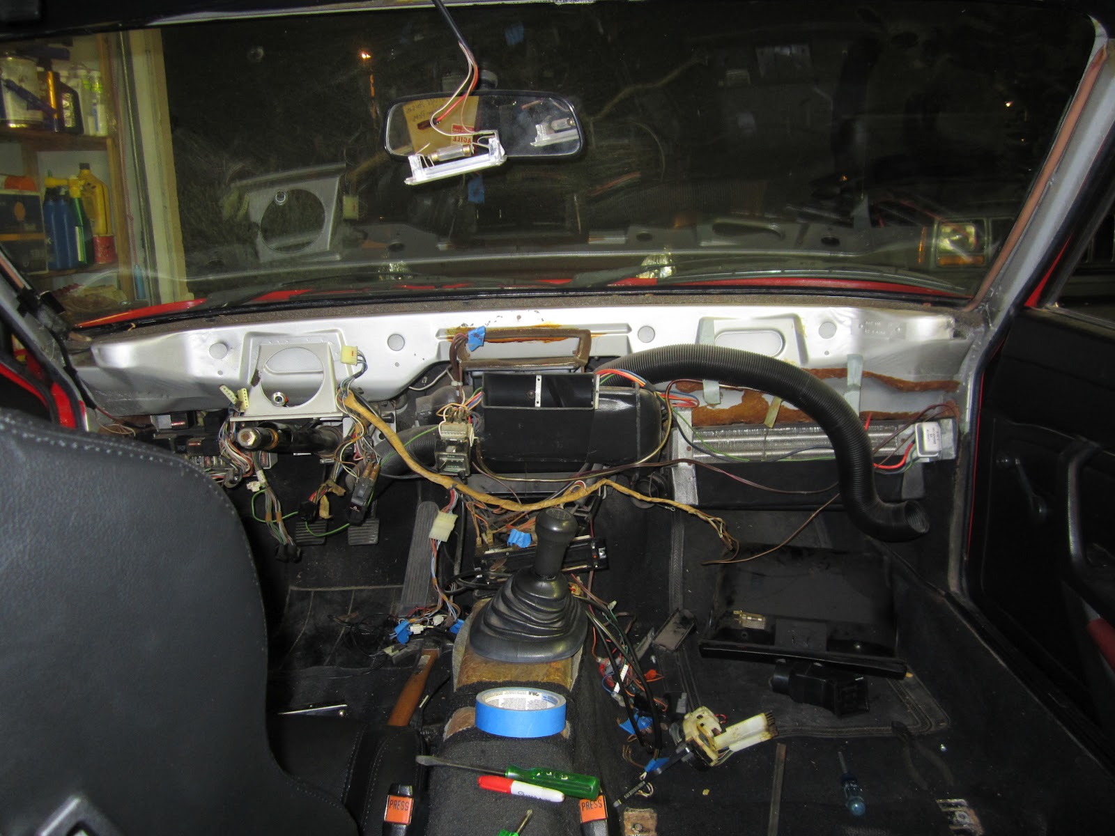
The gauges were pretty easy to get out, but there's a nightmare of wire connections.  Every wire is labeled, but it's still going to be a trick putting everything back together.  With that out of the way, the dash come out!  If you look at the picture below, this is the point where most people would wonder what they had gotten themselves into.  I am one of those people.


One of the problems with the car was that that odometer stopped working.  The speedometer still works, so I've been hopefull I can get it fixed.  As it turns out, it was a simple fix and based on how easy it was to find help on how to fix it, I think all 924's had the same problem at some point in their lives.  Here's the freshly removed gauge.


There is a small plastic pinion gear that I've already removed in this picture that interfaces with the white worm gear near my thumb.  The pinion gear either slides down the shaft until the gear teeth don't mesh anymore, or it cracks and stops gripping the shaft.  Mine had done both of those.  This is a pretty crappy picture, but trust me, there's a crack in it.


The shaft it's supposed to be turning feeds directly into the number cluster, so if you spin it, the numbers turn.  I thought it would be cool to be able to keep track of how many miles I put on the car since the conversion, and since the title already is marked "box C" (odometer discrepancy) with 75k miles on it, it doesn't really matter if I change the reading.  The car is new enough that the numbers won't turn backwards, but I'm only 3500 miles from a round 50k so I shoot for that.  I attach a nail to the shaft with a piece of heat shrink tubing and it's not too difficult to turn by hand.  I don't really want to spin it with a drill since I don't want to risk breaking it and having to pay $400 for a new one.


An hour  later and I'm rolling over to 50k miles.  I got the new gear pressed on there with a little epoxy and I was able to roll it the rest of the way to 50k with the normal input shaft!  For any Porsche people out there trying to do the same repair, it required a C clamp to push the new gear on there.  I also put a plastic spacer between the gear and the number cluster housing because the shaft can slide through the whole assembly, and if that happens the gear will disengage.  I might have loosened things up when I tried to push the gear on by hand and didn't support the other side of the shaft, so the shaft slides through the number assembly with relative ease.  I'd read about other people suggesting the spacer and I definitely think that'll save me from taking this all apart again in the future.


The next step in the deconstruction was to get the heater vent assembly out.  As expected, once it was on the table I found the secret side door that allows you to slide the heater core out without removing the dash like I did.  But that's okay, it was good to get it all cleaned up.  All of the weather stripping turns to dust when you touch it, and the inside of this thing was remarkable filthy, and I mean dirty!  There was residue in there that seemed like engine grease!  With all new seals and a clean interior, I'm gonna be a lot happier when I open the vents.


The other interesting thing I learned from this whole process is how the ducting works.  The car has heat and AC, but they are completely separate systems!  There are 9 vents: 4 for AC, and 5 for heat.

The heater system draws air in through the clam shell on top in the picture above.  There's a fan right inside that blows air through the heater core and out to the vents.  The left and right ducts and the defroster are always getting airflow, and the two foot vents have a damper.  As far as I can tell, you can't recirculate the air, but I may be wrong.  Hopefully the electric heat will be sufficient without the recirc option, but I am in AZ so how bad could it be?  I tested the motor and it spins, so there must just be a problem with the switch or wiring.

The AC system (which is the next piece to come out) is located behind the glove box and suck air in from there (no fresh air option).  A separate fan sucks air through the evaporator and sends it down two ducts.  The smaller of the two goes to a vent below the passenger side dashboard.  The larger one serves the driver's side under dash vent and two center vents.  There's no damper, so you'd have to close off vents to reroute if you wanted.  The wiring looks suspiciously different, so I'm thinking the car didn't originally have the AC option and this was added later.  However it worked out, I'm definitely looking forward to the crotch level vent that I've only ever enjoyed on my friend's early 90's Cherokee!

Monday, April 30, 2012

Brake Problems Finally Solved!

I've been having a battle with the brakes ever since I bought the Porsche.  I knew they didn't work well before buying it, but figured all it would take is bleeding some trapped air out.  Well, when I got her home, I find out one of the bleeder screws is broken off.  So that explains why the spongy brakes hadn't been fixed.  The next problem was finding the correct bleeder screw replacement.  Then to get the broken one out I had to heat it with a torch, which required rebuilding the wheel cylinder. 

Okay so I had that all done a while ago and never had a chance to finally bleed the brakes.  Well I finally got to it a week or so ago and can't get it to work.  The way it normally works is you push down the brake pedal to build pressure in the brake lines, then crack open the bleeder screw and let the air bubbles flow out.  You keep doing that until it's all fluid and no air coming through the lines.  I had my wife pumping the pedal while I worked the screw open and closed, and to my dismay there are only spurts of air coming out and no fluid.  I finally get the idea that maybe the cylinder is dry and leaking and needs to be primed, so I take it out again, fill it up with brake fluid and get it all lubricated and put it all together.  Still nothing but puffs of air even after pumping 50 times or so. 

A week later I've tried a few other methods of pumping the brake with the same results, but now a friend has lent me his vacuum bleeder.  Basically, this thing works backwards of how it works when you pump the pedal.  You draw a vacuum on the outside of the system, crack open the bleeder screw, and that's supposed to pull fluid down from the master cylinder into the brake lines.  Still no luck.  Just air! 

Then I get a brilliant idea.  The only other way I've heard of bleeding a system is to use a power bleeder.  This works by using air pressure to force brake fluid into the lines and gurgle out the master cylinder.  Too bad these cost $90 at Auto Zone.  But I've got a plan.  I take the tank from the vacuum bleed kit and fill it with fluid.  Then I hooked one hose up to the bleeder screw and the other end I plugged with a nozzle from my air compressor.  I set the regulation to 20 psi and let her rip!  I got my wife to keep an eye on the master cylinder reservoir so she could warn me if I created a geyser.  She looked a little worried when I put on safety glasses. (shouldn't she just be glad I was wearing them and not upset that I felt I needed to wear them?) 

Operation was a little slow, but soon we could hear bubbles hissing through the master cylinder and you could see fluid going in on my end.  I had to squeeze the tank from the vacuum kit to keep it from misting all over the place.  I also briefly tried 30 psi and that just turned into a mess and I quickly went back to 20.  After 5-10 minutes, the master cylinder tank level had risen a little bit, but a check of the brake pedal proved to be nice and solid!  I couple more pumps and we were able to get the last remaining bubbles out of the system and I think I'm good to go!


Wednesday, April 25, 2012

Compare and Save!

There are quite a few online stores that sell electric vehicle stuff.  It's not a surprise that a lot of it is just stuff they found somewhere else and marked up on their site.  A lot of the time they shrink, blur, or orient the images so you can't see the part number on the label so it's harder to find it online, but if you're clever enough you can usually find it.  I've been looking at a lot of stuff lately that falls into this category and was thinking about my wife's favorite blog site called Regretsy.  One of the things the writer does is compare supposed hand crafted items to mass produced items sold somewhere else online to show you how bold some people can be in their markup attempts.  So here's my EV variant of Compare and Save!

You need one of these contacters to safely turn on and off the power to the motor.  You could buy it here:


OR


You save $87.88 !!!


To keep your motor running cool, add forced cooling with a blower fan.  You can buy it here:


OR


You save $408.89 !!!


You can't power all the original gauges and lights in your car with the 150v battery pack, so you need one of these DC-DC converters to get 12 volts.  This one's actually a lot cheaper than other version even at this EV store, but you could buy it here:


OR


You save $63.31 !!!


Your braking power is normally "boosted" off of vacuum produced by your engine.  In order to maintain your braking power you need a vacuum system that you could buy here:


OR


You save $323.88 !!!

Edit: This pump didn't actually work!  You saved too much by buying it.  See this post for a better option (that actually costs less in parts but requires a little fabrication).
http://electricporsche924.blogspot.com/2013/01/exciting-day-and-new-challenge.html


So in just 4 items I've already saved around $900 by shopping around!  But can you put a price on convenience?  Granted not all of these are direct comparison.  Some of these are kits with a few bolts and hoses and I'm just comparing with the most expensive part of the system, but you get the idea.

But seriously, check out www.Regretsy.com because it's pretty awesome!

Wednesday, April 11, 2012

WarP 9 Motor Performance Predictions


Before I start, I want to make it clear that any use of this information to design your own car is done at your own risk.  I take no responsibility for anything you choose to do with this data.  If your car doesn’t work the way you want it to, that’s not my fault!  Okay, with that behind me let’s get into it.

I am still waiting on my motor adapter plate to get finished, so progress is still slow.  In the meantime, here’s some info on motor performance that might be interesting to you.  Before I jumped into this project, I wanted to have a good prediction of the performance I would be getting.  I didn’t want to start driving and realize I should have started with a different car, motor, battery pack, controller, or anything else.  One very important piece to that puzzle is knowing how much torque you can get out of your motor.  More importantly, I needed a torque-speed curve.  I’m only going to discuss the WarP 9 here, but I looked at a few other motors as well (mentioned in my last post). 

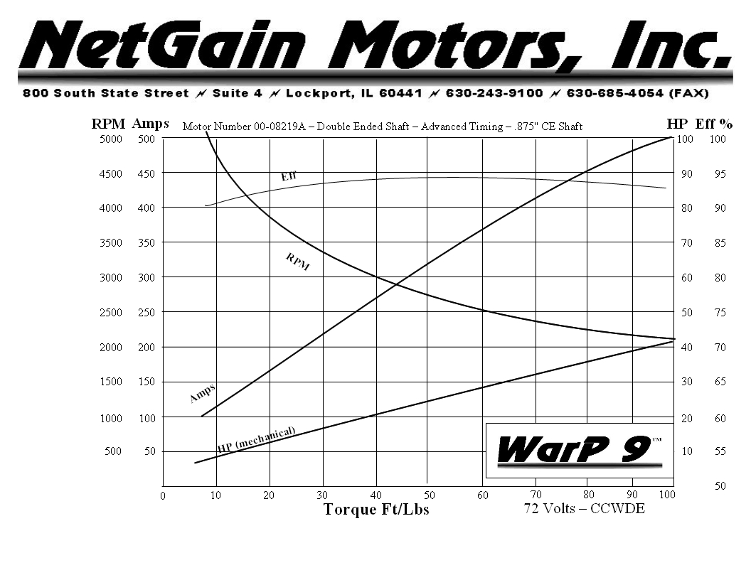
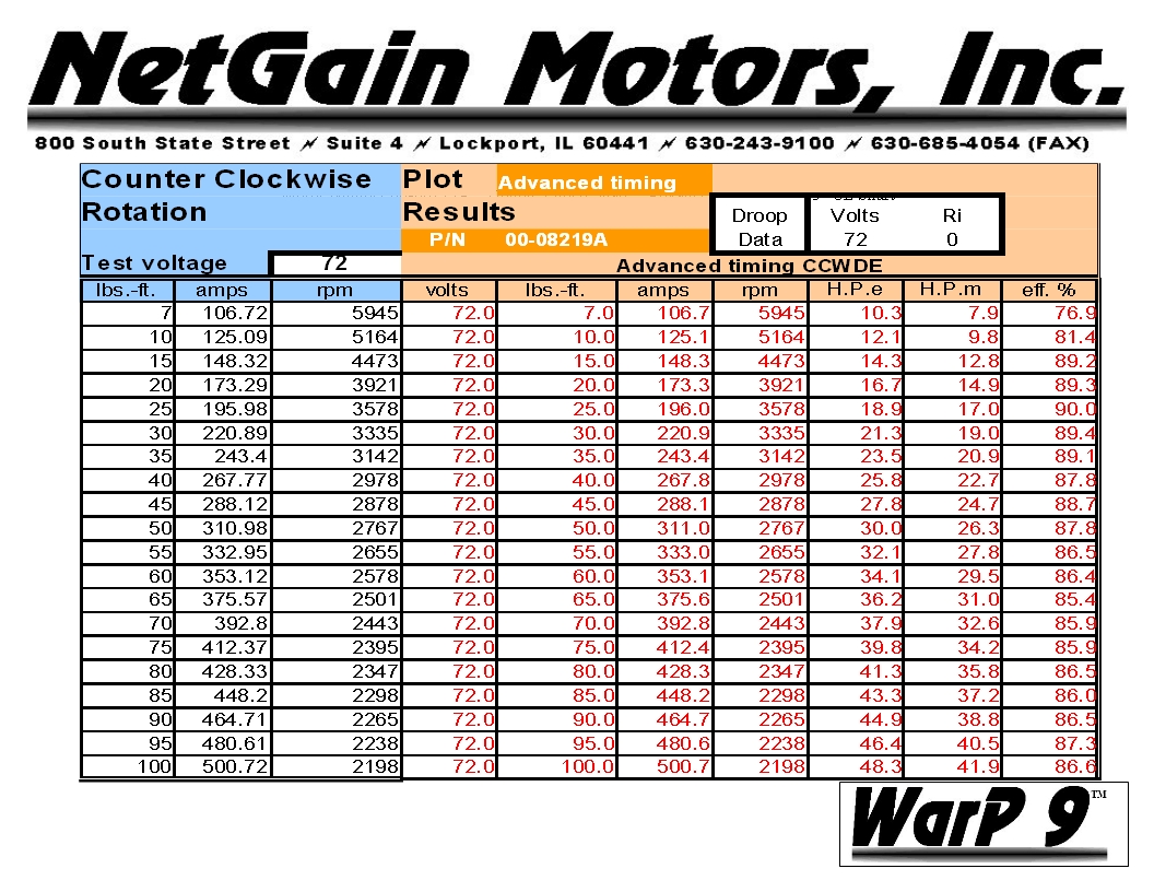
Netgain’s website has a lot of these charts and tables available for you to use.  Here are the links for the WarP 9 data for motors manufactured after 7/1/10.

Unfortunately, the data only goes up to 500 amps.  For a lot of people, this is entirely adequate since they have a controller rated for 500 amps output to the motor.  If you intend to drag race, that’s not going to cut it.  Electric drag racers commonly run 1000-2000 amps through their motors to get more torque.  So how do you figure out how much torque you’re going to get beyond 500 amps?  There is a common rule for series wound motors that says the torque is proportional to the current squared.  The equation looks like this:

Torque = Constant x Current^2

From Netain’s data, at 500 amps you get 100 ft-lb of torque.  Using that data point, the constant can be calculated to be 0.0004, so now you get this equation:

Torque = 0.0004 x Current^2

Let’s say you want to know the torque output at 1000 amps.  With that equation, you would predict 400 ft-lbf…sweet!  Too bad that’s not what really happens.

Okay, if you plot out the data, it looks like a fairly straight line, so let’s just use the slope of the last two data points and see what happens.  You get a linear relationship that looks like this:

Torque = 0.2486 x Current – 24.3

Using this relationship, at 1000 amps you would predict 224 ft-lbf.  Unfortunately, you can’t count on that either.  So why can’t we use either of these methods?  Well you can if you aren’t extrapolating the data too far from the actual data, but doubling the range is out of the question.  The problem is called saturation.  First let’s discuss how a motor works.

Inside the motor you essentially have electromagnets.  When you were a kid, did you ever wrap wire around a nail and hook it to a 9v battery to pick up paper clips?  The force coming from an electromagnet is proportional to the number of turns (windings around the nail) multiplied by the current going through the wire.  Since a series wound motor uses electromagnets for the stator and the rotor, you get a force proportional to the current squared.  But you can’t just keep increasing the current and expect the square relationship to continue indefinitely. 

When you apply current, you create a magnetic field.  Anything made of iron has low permeability, meaning the field flows easily through it…sounds like something from Star Wars.  But it can only flow so much.  Similar to a garden hose, at some point, opening the valve more doesn’t produce any more water flow.  This phenomenon in the electromagnetic world is called saturation.  Certain areas of the iron core used in the motor’s rotor and stator will start to saturate as the field is increased.  At this point, the magnetic field (or flux) will have to find another path, which is probably through air.  If it doesn’t pass through the iron, you don’t get usable force out of it.  Eventually the entire part will become saturated and no matter how much current you apply, the force will not go up any more.  Okay, enough with the physics lesson.  This is what I did to solve the problem.

I decided that the saturation could be accounted for by making the exponent in my first equation a variable instead of a constant.  That variable should be a function of current and inversely proportional to it (i.e. it decays with higher current).  I found a few bits of data on the internet for current above 500 amps and fit it in with the Netgain data.  The result looks like this:

Torque = Flux Constant x Current^Exp
Exp = 2.0615 – 0.0002 x Current
Flux Constant = 0.00051

This is the result.  You can see that the equation fits the Netgain data fairly well, and as would be expected, the slope gets lower as the current gets higher.  If anyone out there has good data on the current WarP 9 motor, please let me know and I can use it to enhance this graph.  You can also see from this graph that using the squared rule does not fit the data well at all.

The next piece of the puzzle is the torque speed curve.  Why do I need to know this you ask?  Well this tells us how fast the motor will spin with a given voltage and current.  You can use it in a variety of ways.  Let’s say you know you need 50 ft-lbf of torque to climb a hill in a certain gear and you want to do it at 50 mph.  You could look at this graph and determine how much voltage you need to supply to the motor to achieve this.  From a different angle, if you want to know how long you will have your maximum torque in a certain gear, you can use this chart to determine that as well.  Again, we want to extrapolate this data beyond the range of what’s provided by Netgain. 

We’ll start with the governing equation.  It is commonly accepted that RPM, Voltage, and Current are related with this equation:

RPM = K x Voltage / Current

where K is the motor constant.  If you use this equation to calculate K for the Netgain data, you will find out that K is, in fact, not a constant.  If you plot K versus Current, you will find that the relationship is fairly linear.  That means we can easily calculate K as a function of current.  I found that the data matches a little better if you split it in two sections and use a linear relationship for K above 300 amps and a polynomial relationship less than 300 amps.  You can see the curve fits in the following chart.

From this, we can get the following equation for K:

K = -0.00006 x I^3 + 0.0809 x I^2 – 9.3578 x I + 8982.3                 For I < 300 Amps
K = 17.69 x I + 6404.8                                                                       For I > 300 Amps

In the next chart I’m comparing the actual data with the calculated data and you can see it fits quite well.


From here you can extrapolate even further and create curves for various voltages.


And now I'm ready to make my performance predictions.

Thursday, March 29, 2012

Motor Choice


There are lots of electric motors out there and there’s a lot to consider when picking one out.  Most people, I think, have a misunderstanding of what will be best for them.  Here’s a compilation of what I’ve learned and how I chose the WarP 9” motor.

Brief Overview of Motor Types:
Series Wound DC Motors – These motors are by far the most popular among EV conversions.  The reason for this is that they are relatively cheap and produce a large amount of torque for a given amount of current.  This means you need less current to get your car moving.  Since current is somewhat of a commodity in the EV world, you get more bang for the buck with this motor.  In addition, a relatively inexpensive and simple PWM controller is used to drive this motor.  These motors are basically the same as the motors used in forklifts except that they have been modified for higher voltage and higher RPMs.  Some people even get used forklift motors for their car since they can be quite cheap.

DC Permanent Magnet Motors – These motors operate similarly to the series wound motors except that they have permanent magnets for the stator instead of a coil.  They do not produce as much torque for a given current when compared to series would motors.  They also are probably more susceptible to high temperatures than series would motors, though I don’t know that for sure. 

AC Motors – These motors are driven off an alternating current.  You achieve greater efficiency with these motors and can easily incorporate regenerative braking, which is why I think they are used on most hybrid cars.  The downside is the controller for this motor is complex and expensive.

Comparison of Series Wound Motors:
I picked the series would motor type due to the cost involved and the high torque output vs current as mentioned above.  The next question is what brand and size.  I’ll assume that all manufacturer’s motors are equivalent in quality, reliability, etc, so this question is more about what size and winding parameters do I want.  I’m going to compare 4 motors that are popular among EV conversions: Impulse 9, Warp 9, Warp 11, and ADC 9.  The three 9 inch motors are approximately the same diameter but are wound differently.  The Warp 9 and 11 are supposedly wound similarly but are different diameters.  One thing to remember is that the power you get in is the power you will get out (neglecting variations in efficiency, which are similar for all motors). 

9 Inch Motors - Changing the windings affects the speed (RPMs) of the motor for a given voltage and current.  This means that one motor will spin fast with low torque and another will spin slow with high torque since the power in has to equal the power out.  FYI, power in is the voltage multiplied by the current and power out is equal to the torque multiplied by the rotational speed.  Depending on how much voltage and/or current you can supply to the motor in addition to how quick you want to accelerate and the desired top speed will affect which of these is best for you.  The Impulse 9 is wound for higher speed and lower torque, the ADC 9 is wound for higher torque and lower speed, and the Warp 9 is somewhere in the middle.

Warp 9 vs Warp 11 – Supposedly these two motors are identically wound.  If that is so, then for a given force between the windings (the field and armature) will produce a different torque because of the different moment arm (diameter of the motor).  This means for a given internal force, the Warp 11 will produce around 20% more torque than the Warp 9.  Consequently due to the conservation of power rule, the speed of this motor will be slower in the 11” motor than that of the 9”.

The chart below shows a comparison of motor RPM vs Current at a constant voltage.  Up to about 500 amps this is based on manufacturer’s published data.  More info on extrapolation later.


The next chart shows a comparison of torque vs RPM at a constant voltage.  Again, up to about 500 amps this is based on manufacturer’s published data.


 And one more chart that shows a comparison of torque vs current for each of the motors.


 Most people look at this data and say I have a 500 amp controller and I can get 154 ft-lbf of torque from a Warp 11.  I’ll buy that one because it’ll give me the best acceleration.  Well, not exactly.  This is a correct statement technically speaking but it may not really be what you want.  For many people, I think this is common mistake made when designing your car and here’s why. 

I’ll start with a typical conversion setup.  144 volts is a common battery pack size because it allows you to use most of the base model controllers and is easily achieved with 6 or 12 volt lead acid batteries.  We’ll also assume you have a 500 amp controller and the batteries are sized to allow you to drive 500 amps to the motor.  Many people would assume you can get 154 ft-lbf for as long as you keep your foot on the pedal.  If this were correct, you could make it from 0-60 mph in a blazing 4.75 seconds.  I see a lot of people on evalbums.com who are building their car with very similar specs and expecting 0-60 in under 6 seconds.  I’m sorry to tell you that this is not going to happen.

Here's what is more likely to happen.  With 154 ft-lbf of torque coming from the motor, you can easily peel out in 1st gear, but it won't last for long.  I’ll assume your pack voltage sags to 120 volts at 100% duty cycle from the controller.  At this point you have 60 kW of power in and we’ll assume you get the same power out.  At 154 ft-lbf, the maximum motor speed is 2300 RPM before you reach your maximum power output.  If your overall gear ratio is 14:1, you are only traveling 12 mph when the torque will begin to taper off.  So you change into second and get a new burst of speed, but that gear starts to runs out at 21 mph.  There are a lot more factors than I previously mentioned, but you’ll find that you can easily spin the wheels in 1st gear, but it takes you about 9 seconds to get to 45 mph (if you start in 2nd gear) and an excruciatingly long 20+ seconds to get to 60 mph.  Here’s a plot of a simulated run of the first 10 seconds if you shift at 3000 rpm.  I’ll describe more of the parameters I used in a future post on performance predictions.


So now what do you do?  Well, what this means is that you need to determine what’s most important to you.  The only way to get those super fast speeds like you see with the White Zombie drag racer is to have lots of current, and more importantly, very high voltage (higher voltage means more peak horsepower, which in turn means you get max torque up to a higher motor speed).  I’ll talk more about that in the future post on performance.  For now, we’ll assume you’re on a budget and want to stick to a low voltage (160v nominal or less) controller and battery pack.  The problem we ran into in the example above is that the battery pack reached peak power output at a low motor speed.  This causes you to shift early and reduce your gear ratio (i.e. less torque at the wheels and less acceleration).  If you trade some low end torque for higher motor speed, you will get that max torque output for a greater RPM range.  The extreme case for this (in our set of 4 motors) is the Impulse 9.  This motor is a good choice for people with lower battery pack voltage.  You can see from one of the charts above that it only gets 70 ft-lbf of torque at 450 amps, but at 120 volts you will get that same torque all the way up to 4650 RPM, or around 24 mph.  With this motor and the same example as above, you would be able to accelerate to 45 mph in 8 seconds and to 60 in about 14 seconds.  This performance is comparable to that of a normal car.


The Warp 9 was redesigned in 2010 and I’ve seen groaning on some forums from people who didn't like that Netgain lowered the output torque for a given current.  Well, they did it for a reason, and I presume it’s exactly the sort of thing I described above.  Targeting the largest audience who use a low voltage controller, the newer designed Warp 9 will give you a good balance of peak and high speed torque. 

So what can we conclude from all this data?  If you are not running a high voltage system, you will probably be disappointed with the performance of a large motor.  It also tells you that you need to do some math if you really want a high performing vehicle.  Just putting a big motor (or lots of batteries for that matter) in your car will not make it fast if you don't apply it properly.

For me, I want more of a hot rod, meaning more off the line torque.  That’s why I picked the Warp 9 over the Impulse 9.  But in order to meet my 0-60 goals, I was forced to consider a higher than typical battery pack voltage and controller current.  After figuring out what was economically feasible for me, this motor gave me the fastest 0-60 time when compared against the ADC 9 and Impulse 9.  If I were using a different battery pack or controller, that may be different.  Like I’ve said before, more info to come in a future post on performance predictions.