Wednesday, March 6, 2013

Battery Charger Part 1

Last time I told you I was going to remove a battery amp limitation from the controller and report back. Well, I changed it from 17 to 170 amps and what a difference it made!  It's like driving a real car!  Right now I'm set to 170 battery amps max and 300 motor amps max and acceleration is really pretty good.  Like as good as any typical passenger car.  Someday I'll see how 833 motor amps feels like...

Back to the topic of the day; the charger.  Part of the reason I don't have all my batteries installed in the car yet is that I have no way of charging them.  In order to save money (and have more fun!) I'm building my own!  Luckily I have a good friend who's blazed the trail on this one and already has a circuit designed for me.  He ordered some printed circuit boards (PCBs) that he designed and now it's time to put everything on them.  The boards cost more the bigger they are, but you get a real break in the price if you stick to a certain size, so Joe used a few surface mount parts to keep it within the size limit.  If you don't know what those are, it's the tiny little pieces that you might see on a computer mother board that's typically placed and soldered on with a machine.  Luckily we had pretty good success putting these on and here you can see the nearly finished board next to a bare PCB.  You might ask why I've got two of these and that's because Joe wanted one and the minimum order is 4 boards.
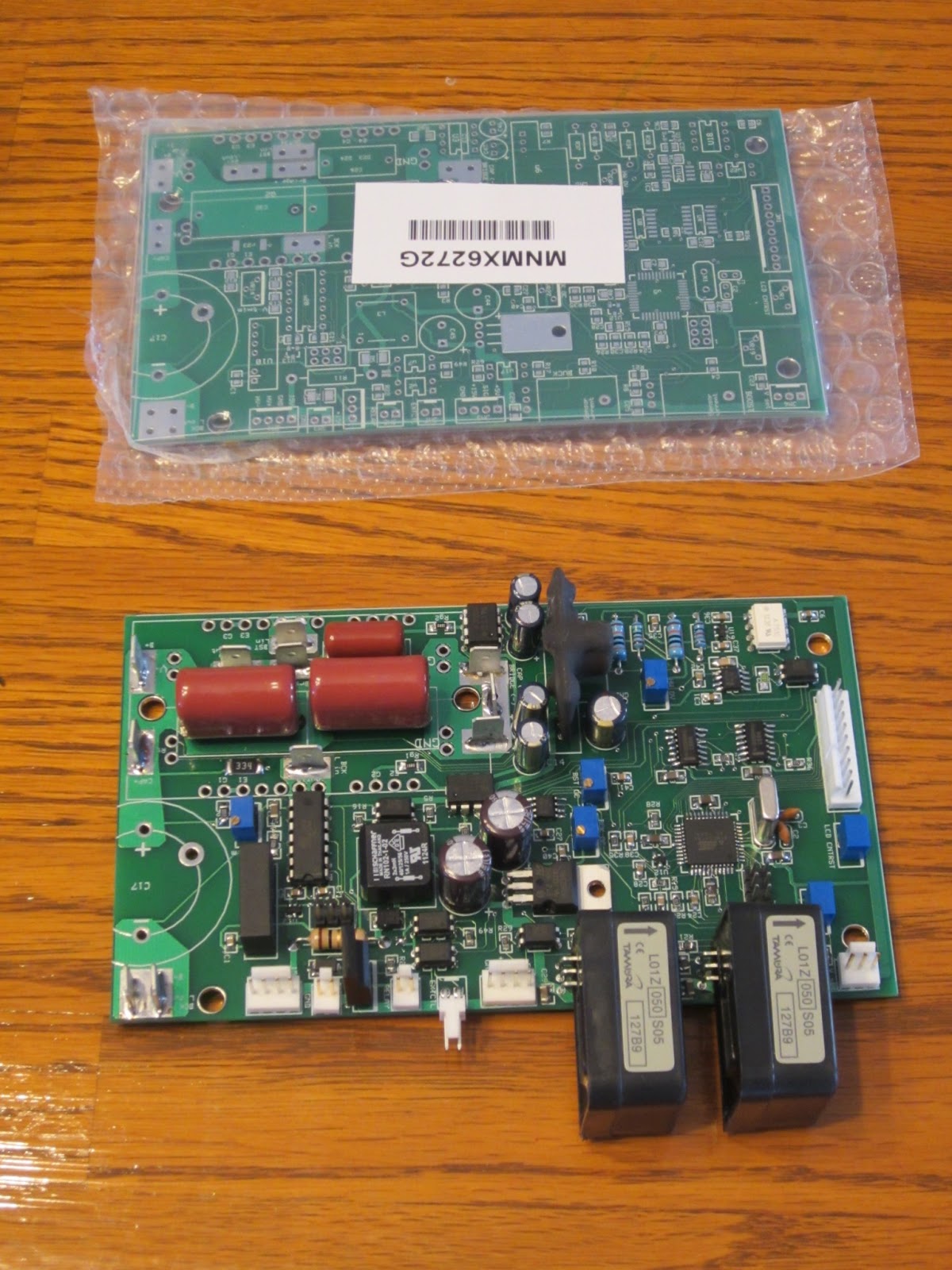

The controller works like this.  You plug either 115 vac or 230 vac into the controller.  It rectifies the signal coming in, then boosts the voltage up to about 350 volts with a boost converter.  After that is a buck converter stage that reduces the voltage to whatever is required to drive a certain amount of current into the batteries.  The charger continues to do this until a peak voltage is reached.  In my case it will be about 250 volts.  Then the charger will vary the current going into the batteries to maintain that voltage.  The current will slowly drop off, and when it goes below a certain threshold the charger will shut off.

What's a boost and buck converter?  Look it up on Wikipedia.  Both require a large inductor.  In fact, the inductors are big enough, it would be difficult to find one that you could purchase directly.  So what to do?  Make your own of course!  Here are the supplies: 14 gauge magnet wire and a magnetic core.  I'm using 14 gauge wire because I'd like to charge the batteries fast, and that requires a lot of current.  14 gauge wire with 90 °C rated insulation is good up to 25 amps and this has 150 °C insulation so I'm guessing I should be good to over 30 amps.  With a 230 volt 30 amp circuit I can get into the low 20's of amps, but I need to wire up that outlet before I can do that.  At 20 amps, I could complete most of the charge for fully discharged batteries in 3 hours.  After a round trip to work it would be less than half that.


Here's my 4 year old daughter helping me wind out the wires.  26 feet of wire is a lot to handle on your own!


And about an hour later, here they are!  30 amp rated 900 milli-Henry inductors!  Man, my fingers hurt.  And even though I'm writing this a day later...they still hurt.


Next up, finishing and testing the charger, and designing the battery monitoring system (BMS).  I've also got to finish those dang battery boxes!  So many details...

Thursday, February 28, 2013

Car Show

The car show that was scheduled last week on Wednesday was rained out, but luckily they pushed it to Wednesday this week.  I made it, and here's how I got there!


Two days before the show I decided I needed to fix the leaky heater core.  It's been leaking since I first put it in, but it's such a pain to get at I never bothered with it.  Well, since all my coworkers will give be crap about it and I'm tired of washing coolant out of the driveway it's time to get my hands dirty.  A few hours later I've got a paper gasket and some RTV in the flange and it's leak free!


I've driven the car around the neighborhood a bit, but not a whole lot.  The trip meter just rolled over to 0.1 miles.  It's still very sluggish and only seems to get up to about 5 mph (not enough to register on the speedometer).  There is a parameter in the controller that allows you to limit the maximum motor amps, and I'd set that parameter to 1 for initial testing (corresponds to about 104 amps) and later moved it up to 2 before I first drove it.  It seems worthwhile to bump it up to 3.  At 200 amps I figure I have 16 ft-lb of motor torque, and assuming friction, rolling resistance, hills, etc, I can see why that would be pretty slow.  Using the current squared rule, I should get 2.25x the torque by upping the amps to 300.  A friend is coming over with the car trailer soon so I don't have much time to try it out.  Acceleration is noticeably better, but top speed is hardly any better.  The trailer shows up the night before the show and we load the car.  To get up the ramps, my friend actually has to push a little.  Good thing there aren't any hills to climb at work!


The next day after a restless night, we drive in to work.  We unload the car and drive in (slowly).  Inside the campus there's a long stretch where I manage to accelerate to white knuckle speeds of 9 mph!  Good thing there's a 10 mph speed limit so I can pretend to have an excuse.  When I park the car I already have a crowd forming around me!  Too bad I had to shoo everyone away because I was already late for a meeting, but I get to breathe a sigh of relief that I'd actually made it!  0.5 miles on the odometer, my longest drive ever!

The show was a lot of fun.  60 different cars of all types: 3 Ferraris, a top fuel drag racer, a bunch of classic and modern muscle cars, a couple VW busses, and one electric car.  After 2 hours of answering questions I have to once again close up shop and go to a meeting.  


I'm disappointed in the driving performance.  With the way it's set up I should have plenty of torque to get around and with 80 volts I should be able to go at least 35 mph.  After work I pull out the laptop again and plan to take some real time data while we drive out.  Hopefully I can find something wrong that I can fix.  Of course it can't hurt to toggle the current setting up another notch to 4.  Acceleration is noticeably better, but this time I max out at 11-12 mph (the speedometer is barely above the first line!).  I timed my exit so I wouldn't have anyone waiting on me, but my dad (who also work here) zipps up in his TR4 and heckles me a bit for being a slow poke!  We loaded up the car and drive it safely home.  All in all it's a good day.  I'm fairly confident that there's something in the software that's severely limiting the performance.

On the drive back to the trailer, my friend took a couple screen shots of the data as it streams by.  The current commanded is about 60, which corresponds with about 100 amps, and the current feedback is the same.  So for some reason it doesn't seem to want to go above that. 
All these parameters have a max value of 512, so the value divided by 512 gives you the percent of max (except the thermistor).  The current readings are incorrect because we've tricked the controller by changing the current sensor and didn't change the software.
Green = Thermistor Reading (73 °F)
Red = Throttle position
Pink = PWM (about 17%)
Blue = Motor Current Feedback (controller thinks it's about 60 amps but it's really 100 Amps)
Light Blue = Battery Amps (controller thinks it's 10 amps but it's really 17 amps)


Luckily, after looking at this data, Joe figured out the problem the next morning!  When we tested the controller the first time back over the Thanksgiving weekend, we had it hooked up to some RC plane batteries and a treadmill motor.  In order to keep from ruining the batteries (which we probably did anyways), we changed one of the parameters to limit the current from the batteries to 10 amps.  We never removed this restriction, so I'm still limited to 10 amps coming out of the battery.  Since the current sensor is calibrated differently, it's actually 5/3 of 10 amps (or 17).  At 80 volts, that's only 1300 watts or 1.75 horsepower, so no wonder we could only go 12 mph!  Most hairdryers put out more power than that.

Stay tuned for an update on the performance after I monkey with the settings this weekend.  Including 0.8 miles at the car show I've now driven a total of 0.9 miles!


Sunday, February 17, 2013

It's alive!!!

That's right folks, I've brought life to my creation.  Today I actually drove my car!  Not very far, but it certainly moved on its own.  Here's how I got there.

I started Saturday morning and worked 14 hours until I didn't have any physical or brain power left.  By the end of the day Joe made the comment "yeah man, your mind is wasted."  I started the day by setting up more batteries to charge.  I got them all up to 3.41 volts, then strung them up in parallel so they could all top off exactly the same.  Here's my brother setting them all up.  Don't cross those wires, there's potential for 10's of thousands of amps here!


 It's also time to finish off the wiring.  Here I'm getting ready to make all the high voltage cables.  I've hooked up all the cable terminals where they need to go, and sheesh there's a lot of them!


And they're done!  Too bad there's a crucial error in here that I didn't realize until taking a last minute look at my schematic at 9 pm.  Luckily it's not a showstopper so I'll correct it when I pull the batteries again.


Here's the manual switch for the high voltage system.  When I flip this I'll get +230v to the controller through a precharge resistor.  When I turn the key, the B- contactor closes and completes the circuit to the controller and precharging starts (which takes about 1.5 seconds).  The B+ contactor closes when you first start to move the accelerator pedal, initially it does nothing.  In order to protect the controller and make sure it has a chance to precharge, you have to push a little red button on the dash that activates the switch hooked to the pedal.  Got it?  Okay, let's move on.


And here's the point where my mind started falling apart.  Joe showed up with his laptop and computer so we can test it out at high current.  Back over the Thanksgiving weekend we tested the controller at 80v and about 20 amps, but that's were we stopped.  There's basically no easy way to get higher current or voltage without hooking it up to a car.  It'd been so long I forgot how I we still had more to test on the controller.  At this point, Joe took out his phone to take a video of me starting it up for the first time.  I think his words were something along the lines of "If it works, we've got a great video of it.  If it's a spectacular failure, at least we'll have a cool video for all the effort!"  Luckily, "all" we heard when I hooked up power was the clack of the contactor closing.  After getting the motor to spin out of gear, we lifted the rear end, popped it in 4th, and spun up the tires.  Nice...


So that was Saturday.  Today I had a little tidying up to do before I was ready for a test drive.  All the cables were hanging out the bottom, a few things weren't screwed on very well, and I wanted to check over a few things I did in my frantic state the night before.

With everything in order I clear out all the tools, drop the hood, and hop in the car.  I start backing down the driveway (yeah!!!) and start turning so I can avoid running into my Jeep at the end of the driveway, and what??? why isn't the steering wheel turning???  I get to the end of the driveway and it feels like the steering column is locked.  I drive back up the driveway and shut everything off.  Ok, whew, it worked and nothing blew up.  But why the heck can't I steer?  Long story short, 7 months ago I made a major error that somehow didn't surface until this moment.  The motor mount bracket that cleverly snakes around the steering shaft isn't so clever after all.  If you turn if far enough, one of the clamping bolts on the shaft runs into the bracket.  Oh well, nothing that can't be overcome in and hour with a dremel, a die grinder, and a reciprocating saw.  I'll add that to the list of things to fix properly between now and taking it on a major road.

So back in the car, down the driveway, do a couple laps around the cul de sac, and it works!  I still have a bit to go to get it ready for the show, but overall I'm pretty happy.

Thursday, February 14, 2013

Time is running out...

Dang, I had a nice long update written out here and somehow it didn't get saved.  Oh well, you'll just have to deal with this.

I've got 5 days left before the car show, so it's definitely go time.  A week ago I even took a day of vacation to try and catch up because I was falling behind!  A few days ago I admitted to myself it was going to be too risky to try and drive the car all the way to work.  To get all the way in I'd have to have all the batteries in place.  The problem with that is my charger is weeks away from being ready, so I'm stuck with charging 10 at a time with a small charger.  And charging 10 at a time means I'd have to remove the rear batteries.  It's not really feasible to test the car at full voltage, then remove, charge, and replace them.  A friend at work said he could trailer me in to the show, so I think I'll do that and drive it in from the parking lot on 80v (the front battery pack).  That took a lot of pressure off finishing the rear racks and allowed me to switch to wiring.  So that's the plan, I won't drive it from home but should be able to drive in under my own power.

Speaking of batteries, I started charging them this evening.  The charger runs off 12 volts and needs 300 watts to run at max power, so that means I need to supply around 25 amps.  A regular car battery would be drained pretty fast at that rate, but I've got something way better.  The DC-DC converter I got for the car runs great on 120 Vac, and it puts out over 600 watts.  Just had to sacrifice an old PC cable and here you have it!

Only problem is the fan makes a fair amount of noise.  And that's actually an understatement because it sounds like a small vacuum cleaner is running in my kitchen!  Just 5 hours or so of this and I'll be ready for the next 14 batteries...

So to make up for last week, I can finally say it.  Nice rack!


I finally bolted this baby down and she's ready for batteries.  Though I've got a little more to do before that.  Here are a couple pics of the rear racks in process.  This one's all done except for paint.


And here I've got my liquid cooling pump.  I was sure glad to get this all hooked up and not see water leaking out of the controller!

I don't have the pictures yet, but I've got most of the 12v stuff wired up.  That includes the fans, pumps, etc.  All I have left are the contactors and power to the controller.  Once that's done I have the high power cables to build.  Next is putting in batteries, and after that...testing the controller on the real batteries!  Duh duh DUH!  Keep your fingers crossed for me, I'm hoping to do a test drive this weekend.

Saturday, February 2, 2013

Batteries!

A long awaited day has finally come.  I have my batteries!  I planned all along to wait until I'd finished everything that was feasible to finish before ordering the batteries in order to avoid losing out on warranty time.  The car show has pushed it somewhat faster, so I still have a little work to go, but with any luck I'll be ready to start fitting them in the battery racks after this weekend.

They actually arrived a lot faster than I thought.  I ordered them on Tuesday figuring they'd come in next week, but they were actually at the Phoenix UPS freight center by 10:30 Wednesday morning waiting to be picked up!


Ok, enough small talk, it's time to get technical!  A few weeks back, the 787 was grounded worldwide due to lithium battery fires on a couple planes.  Ever since then I've been fielding questions about when my car is going to "inevitably" burn itself into a smoldering hole in the ground.  Well the answer to that is hopefully never, but I have a few reasons to say that.  To start, there are a couple different varieties of Lithium-ion batteries out there.  For years I've been flying RC planes on what we always called Li-po (lithium polymer) packs.  I'm not sure if there really is a difference between the polymer or ion names, but I think they're pretty much the same thing.  These have a lithium cobalt oxide (LiCoO2) cathode and have the highest energy to weight capacity out there.  Each battery has a single cell nominal voltage of 3.7 volts.  Well, all the cell phones, laptops, and now planes that have caught fire also have this style of battery.  In the last 4 years or so, a new type of lithium ion battery has become economically viable, and that one has a lithium iron phosphate battery (LiFePO4) for the cathode.  If you look up LiFEPO4 on wikipedia you'll find some comparisons between the two.  The LiFePO4 battery is 14% heavier for a unit of energy storage, but is inherently much more stable then the LiCoO2 cells.  They have a nominal cell voltage of 3.2 volts, and are more environmentally friendly to their cousins without the cobalt.  I'll let you read more if you want, but it's supposed to be a superior technology.  So why didn't they use that on the 787?  Well, they probably picked out the battery 10 years ago before this type was really available.  Unfortunately, changing battery types at this stage would probably lead to a year's delay in getting the planes back in the air due to the lengthy process required to certify stuff on planes.  At any rate, enough about the aircraft industry, let's get back to my car!

In the last post I listed all the stuff I need to get done in order to be ready for the car show on the 20th.  Since then I've finished 60% of the battery racks, mounted the heater core (for cooling the controller), removed the motor and modified the flywheel adapter (it now has a runout of a mere 0.0004 inches), and reinstalled the motor.  This weekend I need to finish the battery racks, get the liquid cooling system all set up, and mount the vacuum pump.  I also out to tie up some loose ends with the controller.  If I can get that all done, I'll be on a good path to do a first test drive in 2 weeks!  Just in the nick of time to make the show.  Let's cross our fingers that I don't run into any insurmountable snags.

Alright, here's the part you've been waiting for...pictures of the progress.  Here's the interior almost all put together.  Still quite a few things to touch up here, but way better than before.


Here's a single cell for my battery pack.  I also got a bag of stainless fasteners and bus bars to hook them all together.  


Here's the heater core turned into a motor controller cooler.  Took me forever to figure out where to put this, (I've been thinking about it for literally months) and finally figured it out.  It's hung in the perfect place right in front of the AC condenser.


I've got a lot of work done on the racks but apparently I didn't take any pictures yet.  Too bad, I was hoping to work in the line "nice rack" somewhere.

Wednesday, January 23, 2013

Exciting Day and a New Challenge


It’s an exciting day today!  I've passed 5,000 pageviews on my blog (5,146 to be exact).  That means if I’d let Google put ads on there they would have paid me about $1 so far!  I also found out I've been working on the car so long that the people at Ace Hardware know me by name.  I'm not sure that's a good thing.  More interesting though is that the place I work for just announced they’ll have their third “Bring Your Ride to Work” day 4 weeks from today.  I've dreamed about bringing a vehicle in since the 1st annual BYRTW day (which was about 6 years ago), but always ran into problems actually getting my vehicle in to work.  The first year I was planning to take my 64 CJ6 in but a nut stripped out inside the transfer case 100 feet from my house the day of the event.  The second time I planned to bring in the CJ again after finishing the power steering conversion on it, but the steering wobble I was trying to correct with the conversion reappeared 5 days prior to the event.  So now I’m faced with a new challenge: getting my Porsche roadworthy in less than 28 days!  Here’s what I’m up against.  We’ll start with stuff I've recently finished.

Months ago I completely took apart the interior with the intent of restoring the dashboard.  Well, I got the dash 98% complete and never finished it off or put anything together.  Two days ago I decided it was time to put it all back, and amazingly it only took 4-5 hours to do!  And it looks fantastic with the new dash in place.  What the heck was I waiting for?!  Now all I’m missing is the passenger seat.  Sorry, no pics...

Another outstanding part of the system is the vacuum needed to work the brake booster.  For those of you that don’t know, a normal gas engine provides vacuum when it sucks air into the intake.  Historically, this vacuum has been used for all sorts of things like emissions control, crankcase ventilation, cruise control, wiper blade operation, and of course, brake assist.  Since the engine is long gone, I need a dedicated pump.  A lot of EVers use a piston pump because they must be already commercially available.  My friend, Joe, has one of these on his car and the only gripe about it is it’s so dang loud!  In fact, it’s the loudest thing on the whole car. 

By chance, I ran across a rotary vane pump on www.surpluscenter.com that may do the trick.  The benefit of a rotary vane pump is they tend to be quieter.  After finding the product data sheet on it, it appears to have very similar characteristics to Joe’s piston pump, so I’m gonna give it a try.  I also found an automotive fan motor in there and a jaw coupling for a grand total of about $50 (which is about $200 less than any piston pumps I've found) that I just need to mount together.  And here it is!

Now I get to find out if this $50 was a waste or not.   I hooked it up to the brake booster and let it run for a few seconds before pumping the brake pedal.  And it’s definitely working!  After turning it off, I can tell the force to push the pedal is going up after 2 pumps or so.  Only problem is I’m not sure it’s any quieter than Joe’s is.  But luckily when I’m showing it off to Joe, by chance we figure out that if you baffle the inlet it’s actually super quiet!  Win win.

Okay, so here’s what I have left to do:
-      Mount the vacuum pump
-      Mount the coolant pump
-      Mount the coolant reservoir
-      Mount the coolant heat exchanger (heater core)
-      Plumb the coolant lines
-      Finish the battery racks
-      Adjust the motor coupler
-      Order batteries
-      Do a heck of a lot of wiring
-      New tires
-      Alignment
-      Get Insurance and temp registration
-      Complete the charger

Doh!  The charger is not mature at all.  In fact, it’s still in schematic mode.  That’s certainly going to be the long pull, but luckily I have a backup plan.  Joe has a mini-charger that I can use.  It’d be a huge pain to recharge since I’d probably have to disassemble the whole battery pack, but that may be my only option.

Well, what am I doing here wasting time on the computer?  I’d better get out there and start working!  Only 27 days left and a lot to do!

Friday, January 11, 2013

That's where it's all gonna go

Ok, maybe not everything, but I got a lot of stuff to fit under the hood.  Lots of tangible progress since the last post.  The next two pics are of the entire engine compartment.  You can see the motor controller on the left, the potentiometer in the front, the DC-DC converter on the firewall, and the water coolant tank up front as well.  Ok, that coolant tank isn't actually mounted yet, but its got a home.


I made a mount for the vacuum tank, but when I got the controller in I realized they ran into each other.  Not a big deal to move it but whoops!  I'm also not sure I'll need a tank.  After hearing Joe's noisy piston vacuum pump I've decided to try and make a rotary vane pump work.  It's also relatively cheap, but we'll see...vacuum tank, if I use it, is that big black PVC tube.


Here you can see both of my contactors.  They connect and disconnect the battery pack from the motor and controller and are two stages of safety in case I need to disconnect quick for some reason.  you can also see where the big cables are going to hook up to the controller.


Here is the converter that takes the 225v from the main battery pack and steps it down to 12v to operate all the regular stuff in the car.


Here is the potentiometer that tells the controller how hard I'm pushing down on the pedal.  Everything is hooked up and calibrated, I just need to weld one bracket in place that's currently held on with a clamp.


And here's my first clamp casualty.  Normally I clamp parts together, then tack weld them (very small welds just to hold the pieces together), then take the clamp off and do the rest of the welding.  Well this time I figured it was such a small weld I'd just do it with the clamp in place.  When I went to take the clamp off I noticed there was a puddle of liquid metal on one end.  I think these are made of tin or aluminum.  Oh well!