Friday, May 10, 2013

Need more volts

Previously I've been driving the car around on just 1/3 of the batteries, or about 80v, but now it's time to put the rest of the batteries in there.  In the back of the car below the floor I have two battery racks that hold 23 cells.  Actually, they're big enough for 23 each, but I only bought enough for 23.  I guess if later on I want 2/70ths more range I can buy two more cells.  At any rate, the way the batteries are tied down, I can't just leave that empty space open so I need a battery "blank" to fill it in.  My father in law has a ton of scrap wood and woodworking tools, so he helped me put a pair of these together.


As part of the battery monitoring system I added the capability to monitor the temperature of the cells, three spots in each cluster of batteries.  To do that I've got some thermistors, which are resistors that vary resistance as a function of temperature.  Here's one of them soldered onto a wire.


Apparently there's a lot of debate of how to "properly" monitor the temp of your cells.  Some people attach the thermistor to the posts on the cell since they're wetted in the electrolyte.  Other people using lead acid batteries will actually put the thermistor inside the battery so it's directly touching the electrolyte.  I'm going simple and just taping it to the side of the battery like this.


Then I loaded all the batteries in those nice racks in the back and clamped and strapped them down the same way I did with the front batteries. 


Pretty clean look from underneath.  You can see the threads on the four eyebolts that are really easy to access here.  Too bad the aluminum clamps are super difficult to get to, but oh well.


Well that's it for now.  This weekend I'll start wiring it all up!


Thursday, May 9, 2013

Charger Part 3 Plus Other Stuff

I'm moving along pretty fast now and the next thing I want to do is get the batteries charged before I mount them in the car.  Once they're in the car, it'll be a lot more difficult to do without the big charger, and most of them are not balanced.  Here are the remaining 46 batteries hooked up to the mini charger.  Just 30 hours and they should be ready to go!


The batteries already in the car have already been balanced as a set, so I can charge them all at once if I have a charger big enough to do that.  Last time I started smoking the charger due to a short circuit through the inductor's magnetic field that created an inductive heater.  In this picture you can see the metal bracket that holds the inductors in place loops right through them and the screws complete the circuit with the case.  It's gotta go!

 Here you can see my solution.  I've taken a plastic pipe and used it to hold the inductors in place.  All fixed, at least I hope so!

I realized I ever showed a full picture of the charger, so here it is.  Due to some rework, the "Batt" and "AC" labels are unfortunately backwards.

The big capacitor is one of the few remaining parts to be strapped down in the charger, and here's how I plan to do that.  You can also see the fan that'll blow directly onto the inductors to keep them cool.

Apparently after this I didn't take any pictures, so you'll have to take my word for it.  I hooked the charger back up to the car and plugged her in.  After a few minutes charging at 2 amps, still no smoke so I ramp it up a bit.  Over the course of 20 minutes I get the courage to boost it to 7.5 amps into the battery pack and so far so good!  The inductors are a little warm to the touch, but not bad.  Should be better when the fan is blowing on them.

The way these batteries work, they are close to 3.3 volts over most of their charge/discharge cycle.  During charge, the voltage will get up to 3.37 volts for ages.  As they approach a full charge, the voltage will start to rise faster and faster.  Since I have no BMS hooked up, if one of the batteries happen to be more charged than the others, the voltage on that one will start to rise while the others are still stalled out around 3.37 volts.  To avoid having some batteries start smoldering, I was checking to voltages every minute or so.  The charger is programmed to raise the entire pack voltage to 3.45 volts per cell.  Once it gets to that point, the charger will back off on the current to maintain that voltage.  The current will slowly decrease and the charger will turn itself off after it drops to 2 amps.  Amazingly, that's what happened!

So that's not even close to how far I've gotten on the car since last time, but I've been picked away at this post for 3 days so it's time to POST!  Maybe next time I'll be testing the car on 230v...

Sunday, April 21, 2013

Charger Part 2

It's been a while since the last post, but as usual that doesn't mean I haven't been working.  Last time I showed you the circuit board for the battery charger full of pieces.  Well I've come a long ways since then.  If you can see through the next of wires in this picture, you can see the charger half assembled.  Actually, almost all the important stuff is there, it's just missing a couple sides of the case.  Joe has written some basic code and we're testing out the boost and buck phases.


Yikes!  It's plugged into a standard 110 VAC outlet!  But it works!


Initially, we're pumping current into a space heater element, but once that works for a while, I drive the car up and we hook it up to the 80v pack in the car.  It works!  We've pumped 8 amps into the pack with no problems...so far...


Here's the nifty LCD for the charger that will display stuff like the current, pack voltage, etc.


I'm not exactly sure what the point of this one was, but I think it's the outputs of the boost and buck phases.


Next I start working on the battery monitoring system (BMS).  The purpose of this is to keep track of the voltage on each battery to make sure that it doesn't get over charged or over discharged.  It comprises a "master" circuit board and three "slave" boards.  Each slave will be hooked up to 23 or 24 batteries.  It will have three microprocessors that check 7 or 8 cells, reports those voltages back to the master board, takes one temperature reading, sends that to the master, then tells the next micro that it's their turn.  Here's the bare  PCB that I designed and just got in the mail.


After a couple hours of working on them, this is what all three of the boards look like.  It's pretty hard to tell, but I've soldered in around 350 surface mount resistors that are a mere 0.080 x 0.040 inches big.  More on these later.


Ahhh, what have I done?!  I sliced two gaping holes in the floor of the car!  Just below these holes are the two rear battery racks.  Initially I was imagining mounting all the batteries in the racks, then lifting them into place.  After a while I determined there was no way I could make that work because the racks were hard enough to bolt up with no weight in them.  So to make it easier I sliced some access holes in the floor that I can drop the batteries into and hook all the wires up through. I'll put some covers over these later, and the floor will still look like it always did.  No holes to lose my groceries through.


Here's a close up of one of the holes with some batteries in place.  Nice rack!


I'm sure you picked up on it earlier, that I've done some more work on the charger that didn't go so well.  The first test charging the batteries was pretty quick.  Just yesterday we were hoping to fully charge that pack and see if the charger would automatically shut off on its own, but we didn't get that far.  After a short time, Joe noticed a funny smell.  I tried blaming it on every piece of electronics in the room, but it was pretty obvious that it was the charger when a small plume of smoke started to rise from it.  After disconnecting the power, we determined the smoke was coming off the inductors, but strangely they weren't hot at all.  Even stranger was the sheet of aluminum that the inductors were mounted to was smoking hot!

Long story longer I figured out we'd accidentally built an induction heater.  It turns out you can't run a continuous electric circuit through an inductor without creating a single winding transformer.  The alternating current through the inductor induces a voltage in the bracket that goes through it, and since there's very little resistance, the current is fairly high, which makes heat...and eventually smoke.  Good thing is I think I can fix the mounting without too much trouble to eliminate the circuit loop.

Next up I'll be pulling the battery racks out to clean and paint.  Meanwhile I'll charge all the batteries and get them mounted in the car.  Wiring will be a project since I need to hook up an extra wire to each cell to check the voltage with.  I'll also finish up the BMS and do some more testing on the charger.  Then a couple dozen more things and I'm done!

Wednesday, March 6, 2013

Battery Charger Part 1

Last time I told you I was going to remove a battery amp limitation from the controller and report back. Well, I changed it from 17 to 170 amps and what a difference it made!  It's like driving a real car!  Right now I'm set to 170 battery amps max and 300 motor amps max and acceleration is really pretty good.  Like as good as any typical passenger car.  Someday I'll see how 833 motor amps feels like...

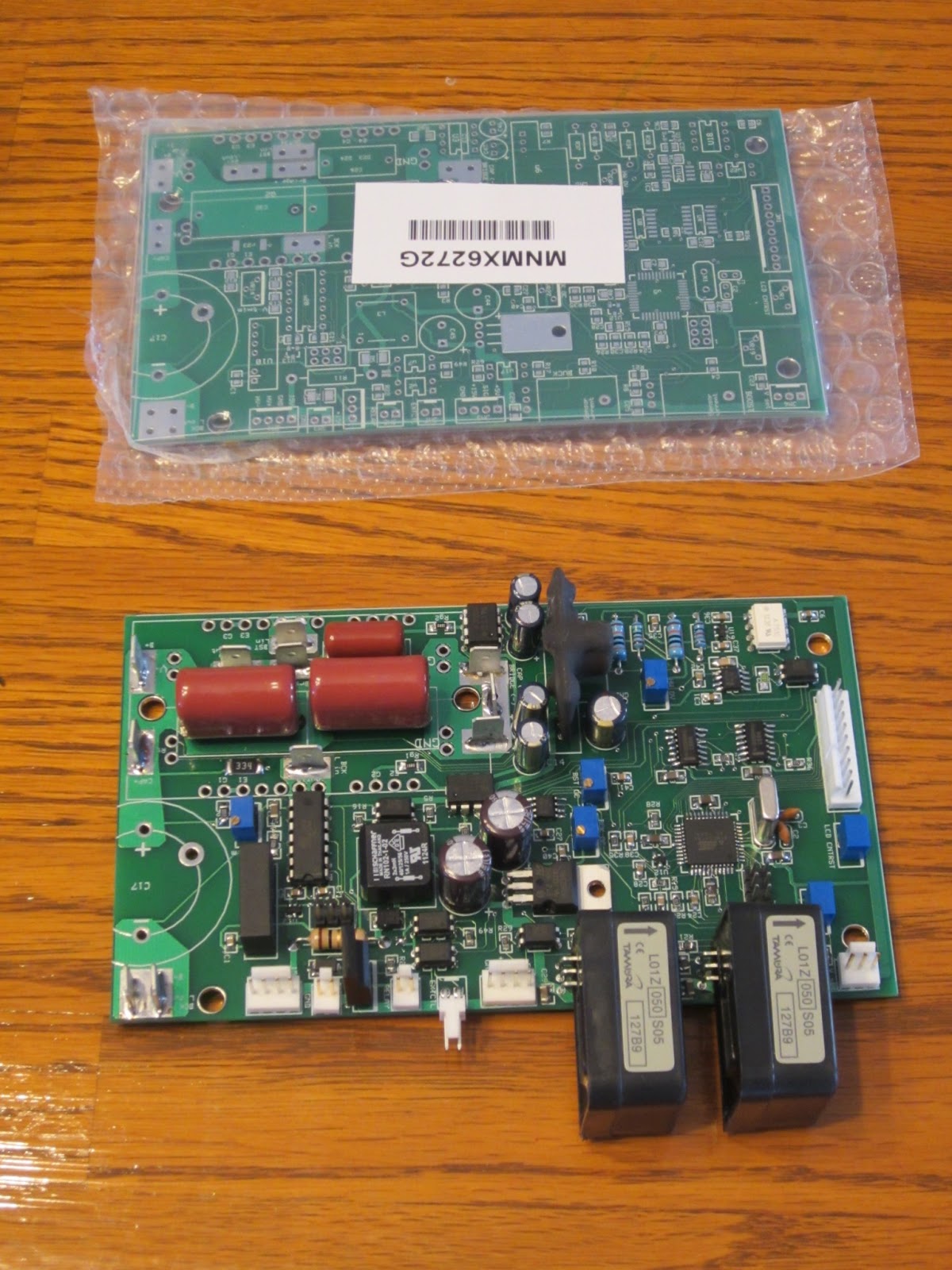
Back to the topic of the day; the charger.  Part of the reason I don't have all my batteries installed in the car yet is that I have no way of charging them.  In order to save money (and have more fun!) I'm building my own!  Luckily I have a good friend who's blazed the trail on this one and already has a circuit designed for me.  He ordered some printed circuit boards (PCBs) that he designed and now it's time to put everything on them.  The boards cost more the bigger they are, but you get a real break in the price if you stick to a certain size, so Joe used a few surface mount parts to keep it within the size limit.  If you don't know what those are, it's the tiny little pieces that you might see on a computer mother board that's typically placed and soldered on with a machine.  Luckily we had pretty good success putting these on and here you can see the nearly finished board next to a bare PCB.  You might ask why I've got two of these and that's because Joe wanted one and the minimum order is 4 boards.


The controller works like this.  You plug either 115 vac or 230 vac into the controller.  It rectifies the signal coming in, then boosts the voltage up to about 350 volts with a boost converter.  After that is a buck converter stage that reduces the voltage to whatever is required to drive a certain amount of current into the batteries.  The charger continues to do this until a peak voltage is reached.  In my case it will be about 250 volts.  Then the charger will vary the current going into the batteries to maintain that voltage.  The current will slowly drop off, and when it goes below a certain threshold the charger will shut off.

What's a boost and buck converter?  Look it up on Wikipedia.  Both require a large inductor.  In fact, the inductors are big enough, it would be difficult to find one that you could purchase directly.  So what to do?  Make your own of course!  Here are the supplies: 14 gauge magnet wire and a magnetic core.  I'm using 14 gauge wire because I'd like to charge the batteries fast, and that requires a lot of current.  14 gauge wire with 90 °C rated insulation is good up to 25 amps and this has 150 °C insulation so I'm guessing I should be good to over 30 amps.  With a 230 volt 30 amp circuit I can get into the low 20's of amps, but I need to wire up that outlet before I can do that.  At 20 amps, I could complete most of the charge for fully discharged batteries in 3 hours.  After a round trip to work it would be less than half that.


Here's my 4 year old daughter helping me wind out the wires.  26 feet of wire is a lot to handle on your own!


And about an hour later, here they are!  30 amp rated 900 milli-Henry inductors!  Man, my fingers hurt.  And even though I'm writing this a day later...they still hurt.


Next up, finishing and testing the charger, and designing the battery monitoring system (BMS).  I've also got to finish those dang battery boxes!  So many details...

Thursday, February 28, 2013

Car Show

The car show that was scheduled last week on Wednesday was rained out, but luckily they pushed it to Wednesday this week.  I made it, and here's how I got there!


Two days before the show I decided I needed to fix the leaky heater core.  It's been leaking since I first put it in, but it's such a pain to get at I never bothered with it.  Well, since all my coworkers will give be crap about it and I'm tired of washing coolant out of the driveway it's time to get my hands dirty.  A few hours later I've got a paper gasket and some RTV in the flange and it's leak free!


I've driven the car around the neighborhood a bit, but not a whole lot.  The trip meter just rolled over to 0.1 miles.  It's still very sluggish and only seems to get up to about 5 mph (not enough to register on the speedometer).  There is a parameter in the controller that allows you to limit the maximum motor amps, and I'd set that parameter to 1 for initial testing (corresponds to about 104 amps) and later moved it up to 2 before I first drove it.  It seems worthwhile to bump it up to 3.  At 200 amps I figure I have 16 ft-lb of motor torque, and assuming friction, rolling resistance, hills, etc, I can see why that would be pretty slow.  Using the current squared rule, I should get 2.25x the torque by upping the amps to 300.  A friend is coming over with the car trailer soon so I don't have much time to try it out.  Acceleration is noticeably better, but top speed is hardly any better.  The trailer shows up the night before the show and we load the car.  To get up the ramps, my friend actually has to push a little.  Good thing there aren't any hills to climb at work!


The next day after a restless night, we drive in to work.  We unload the car and drive in (slowly).  Inside the campus there's a long stretch where I manage to accelerate to white knuckle speeds of 9 mph!  Good thing there's a 10 mph speed limit so I can pretend to have an excuse.  When I park the car I already have a crowd forming around me!  Too bad I had to shoo everyone away because I was already late for a meeting, but I get to breathe a sigh of relief that I'd actually made it!  0.5 miles on the odometer, my longest drive ever!

The show was a lot of fun.  60 different cars of all types: 3 Ferraris, a top fuel drag racer, a bunch of classic and modern muscle cars, a couple VW busses, and one electric car.  After 2 hours of answering questions I have to once again close up shop and go to a meeting.  


I'm disappointed in the driving performance.  With the way it's set up I should have plenty of torque to get around and with 80 volts I should be able to go at least 35 mph.  After work I pull out the laptop again and plan to take some real time data while we drive out.  Hopefully I can find something wrong that I can fix.  Of course it can't hurt to toggle the current setting up another notch to 4.  Acceleration is noticeably better, but this time I max out at 11-12 mph (the speedometer is barely above the first line!).  I timed my exit so I wouldn't have anyone waiting on me, but my dad (who also work here) zipps up in his TR4 and heckles me a bit for being a slow poke!  We loaded up the car and drive it safely home.  All in all it's a good day.  I'm fairly confident that there's something in the software that's severely limiting the performance.

On the drive back to the trailer, my friend took a couple screen shots of the data as it streams by.  The current commanded is about 60, which corresponds with about 100 amps, and the current feedback is the same.  So for some reason it doesn't seem to want to go above that. 
All these parameters have a max value of 512, so the value divided by 512 gives you the percent of max (except the thermistor).  The current readings are incorrect because we've tricked the controller by changing the current sensor and didn't change the software.
Green = Thermistor Reading (73 °F)
Red = Throttle position
Pink = PWM (about 17%)
Blue = Motor Current Feedback (controller thinks it's about 60 amps but it's really 100 Amps)
Light Blue = Battery Amps (controller thinks it's 10 amps but it's really 17 amps)


Luckily, after looking at this data, Joe figured out the problem the next morning!  When we tested the controller the first time back over the Thanksgiving weekend, we had it hooked up to some RC plane batteries and a treadmill motor.  In order to keep from ruining the batteries (which we probably did anyways), we changed one of the parameters to limit the current from the batteries to 10 amps.  We never removed this restriction, so I'm still limited to 10 amps coming out of the battery.  Since the current sensor is calibrated differently, it's actually 5/3 of 10 amps (or 17).  At 80 volts, that's only 1300 watts or 1.75 horsepower, so no wonder we could only go 12 mph!  Most hairdryers put out more power than that.

Stay tuned for an update on the performance after I monkey with the settings this weekend.  Including 0.8 miles at the car show I've now driven a total of 0.9 miles!


Sunday, February 17, 2013

It's alive!!!

That's right folks, I've brought life to my creation.  Today I actually drove my car!  Not very far, but it certainly moved on its own.  Here's how I got there.

I started Saturday morning and worked 14 hours until I didn't have any physical or brain power left.  By the end of the day Joe made the comment "yeah man, your mind is wasted."  I started the day by setting up more batteries to charge.  I got them all up to 3.41 volts, then strung them up in parallel so they could all top off exactly the same.  Here's my brother setting them all up.  Don't cross those wires, there's potential for 10's of thousands of amps here!


 It's also time to finish off the wiring.  Here I'm getting ready to make all the high voltage cables.  I've hooked up all the cable terminals where they need to go, and sheesh there's a lot of them!


And they're done!  Too bad there's a crucial error in here that I didn't realize until taking a last minute look at my schematic at 9 pm.  Luckily it's not a showstopper so I'll correct it when I pull the batteries again.


Here's the manual switch for the high voltage system.  When I flip this I'll get +230v to the controller through a precharge resistor.  When I turn the key, the B- contactor closes and completes the circuit to the controller and precharging starts (which takes about 1.5 seconds).  The B+ contactor closes when you first start to move the accelerator pedal, initially it does nothing.  In order to protect the controller and make sure it has a chance to precharge, you have to push a little red button on the dash that activates the switch hooked to the pedal.  Got it?  Okay, let's move on.


And here's the point where my mind started falling apart.  Joe showed up with his laptop and computer so we can test it out at high current.  Back over the Thanksgiving weekend we tested the controller at 80v and about 20 amps, but that's were we stopped.  There's basically no easy way to get higher current or voltage without hooking it up to a car.  It'd been so long I forgot how I we still had more to test on the controller.  At this point, Joe took out his phone to take a video of me starting it up for the first time.  I think his words were something along the lines of "If it works, we've got a great video of it.  If it's a spectacular failure, at least we'll have a cool video for all the effort!"  Luckily, "all" we heard when I hooked up power was the clack of the contactor closing.  After getting the motor to spin out of gear, we lifted the rear end, popped it in 4th, and spun up the tires.  Nice...


So that was Saturday.  Today I had a little tidying up to do before I was ready for a test drive.  All the cables were hanging out the bottom, a few things weren't screwed on very well, and I wanted to check over a few things I did in my frantic state the night before.

With everything in order I clear out all the tools, drop the hood, and hop in the car.  I start backing down the driveway (yeah!!!) and start turning so I can avoid running into my Jeep at the end of the driveway, and what??? why isn't the steering wheel turning???  I get to the end of the driveway and it feels like the steering column is locked.  I drive back up the driveway and shut everything off.  Ok, whew, it worked and nothing blew up.  But why the heck can't I steer?  Long story short, 7 months ago I made a major error that somehow didn't surface until this moment.  The motor mount bracket that cleverly snakes around the steering shaft isn't so clever after all.  If you turn if far enough, one of the clamping bolts on the shaft runs into the bracket.  Oh well, nothing that can't be overcome in and hour with a dremel, a die grinder, and a reciprocating saw.  I'll add that to the list of things to fix properly between now and taking it on a major road.

So back in the car, down the driveway, do a couple laps around the cul de sac, and it works!  I still have a bit to go to get it ready for the show, but overall I'm pretty happy.

Thursday, February 14, 2013

Time is running out...

Dang, I had a nice long update written out here and somehow it didn't get saved.  Oh well, you'll just have to deal with this.

I've got 5 days left before the car show, so it's definitely go time.  A week ago I even took a day of vacation to try and catch up because I was falling behind!  A few days ago I admitted to myself it was going to be too risky to try and drive the car all the way to work.  To get all the way in I'd have to have all the batteries in place.  The problem with that is my charger is weeks away from being ready, so I'm stuck with charging 10 at a time with a small charger.  And charging 10 at a time means I'd have to remove the rear batteries.  It's not really feasible to test the car at full voltage, then remove, charge, and replace them.  A friend at work said he could trailer me in to the show, so I think I'll do that and drive it in from the parking lot on 80v (the front battery pack).  That took a lot of pressure off finishing the rear racks and allowed me to switch to wiring.  So that's the plan, I won't drive it from home but should be able to drive in under my own power.

Speaking of batteries, I started charging them this evening.  The charger runs off 12 volts and needs 300 watts to run at max power, so that means I need to supply around 25 amps.  A regular car battery would be drained pretty fast at that rate, but I've got something way better.  The DC-DC converter I got for the car runs great on 120 Vac, and it puts out over 600 watts.  Just had to sacrifice an old PC cable and here you have it!

Only problem is the fan makes a fair amount of noise.  And that's actually an understatement because it sounds like a small vacuum cleaner is running in my kitchen!  Just 5 hours or so of this and I'll be ready for the next 14 batteries...

So to make up for last week, I can finally say it.  Nice rack!


I finally bolted this baby down and she's ready for batteries.  Though I've got a little more to do before that.  Here are a couple pics of the rear racks in process.  This one's all done except for paint.


And here I've got my liquid cooling pump.  I was sure glad to get this all hooked up and not see water leaking out of the controller!

I don't have the pictures yet, but I've got most of the 12v stuff wired up.  That includes the fans, pumps, etc.  All I have left are the contactors and power to the controller.  Once that's done I have the high power cables to build.  Next is putting in batteries, and after that...testing the controller on the real batteries!  Duh duh DUH!  Keep your fingers crossed for me, I'm hoping to do a test drive this weekend.